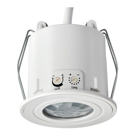
DANLERS CEFL PIR Notas de instalação - Página 6
Procurar online ou descarregar pdf Notas de instalação para Interruptor DANLERS CEFL PIR. DANLERS CEFL PIR 15 páginas. Ceiling flush mounted pir occupancy switch
Também para DANLERS CEFL PIR: Manual de início rápido (2 páginas)

Daylight Control
DISABLED - The ControlZAPP photocell remains inactive and cannot be adjusted. This
function is used where no (or very little) natural daylight is available within a
zone of detection and no dimming functions are required.
ENABLED -
The ControlZAPP photocell is active and the following parameters can be
adjusted: 'Delay before ON',
Style
DIMMING
Click option to enable dimming (and switching) functions. Please check you
have the correct ControlZAPP product for your ballast as indicated on the
ControlZAPP product instructions. (DALI or 1-10VDC).
NOTES:
If dimming a DALI ballast you may also require a DALI Power Supply such
as DANLERS DALIPSU (suitable for up to 20 ballast). ControlZAPP is only
configured for DALI broadcast (closed loop control).
SWITCHING Dimming functionality is disabled - no additional dimming control gear
required. Please ensure you have the correct ControlZAPP product for
switching only.
Delay before ON
'Delay before ON' is period that must elapse before the ControlZAPP control will switch a
connected load ON after the photocell senses that insufficient natural light is available. This
avoids unnecessary switching.
-
To alter 'Delay before ON' timings: Press timer clock to the right of 'Delay before ON'
New screen appears with arrow heads above and below timings (Variable: From 10sec
to 23hrs 59mins 59sec). Quick press for small adjustment. Press and hold to scroll.
Press DONE when complete.
Always turn OFF when light level above threshold
This function can only run after the 'Calibration & Setup procedure is completed.
-
See 'Setup' procedure on pages 8/9.
Delay before OFF
'Delay before OFF' is period that must elapse before the ControlZAPP control will switch a
connected load OFF after the photocell senses that sufficient natural light is available. This
avoids unnecessary switching due to passing clouds.
To alter 'Delay before OFF' timings:
-
Press the timer clock to the right of 'Delay before OFF'.
-
New screen appears with arrow heads above and below timings. Quick press for small
adjustment. Press and hold to scroll. Variable from 10sec to 23hrs 59mins 59sec.
Press DONE when complete.
Occupancy LED
ENABLED
When occupancy is being detected the Green LED glows ON (on the
ControlZAPP control). When no occupancy is being detected the Green LED
is OFF (on the ControlZAPP control).
DISABLED
The green LED will not glow to indicate detection.
Recall Scene
This option enables the load to be permanently ON or OFF for a predetermined time period
scheduled to that switching mode.
DISABLED
No options
ENABLED
Switch ON option or switch OFF option. See Diagram 12. When switched
ON it overrides all other MODE options to maintain the load ON for the time
scheduled to MODE. This could be used when it is desirable for no ON/OFF
switching during working hours but to change to another MODE in out of
hours or for security purposes when on holiday.
Creating additional MODES
Creating multiple modes enables scheduling of diffferent mode functions at different times.
-
Launch App to display 'ControlZAPP' home page. Press 'Modes' button.
-
Press 'New' button in bottom left of screen. New screen appears with a prompt to
'Enter name' flashing cursor (see diagram 13). Type your preferred name (Maximum 30
characters with NO spaces) then press 'OK'.
-
This process can be repeated building up all the MODES you may require.
-
If multiple MODES have been created they will all appear in the grey box at the top of
the screen, some may be obscured (can be revealed by scrolling left /right). The MODE
in use is indicated by a blue line under the MODE in the grey panel (see diagram 14).
and
'Delay before OFF.' See Diagram 11.
Always turn OFF when light level above threshold.
DIAGRAM 11
DIAGRAM 12
DIAGRAM 13
DIAGRAM 14
PAGE 4
