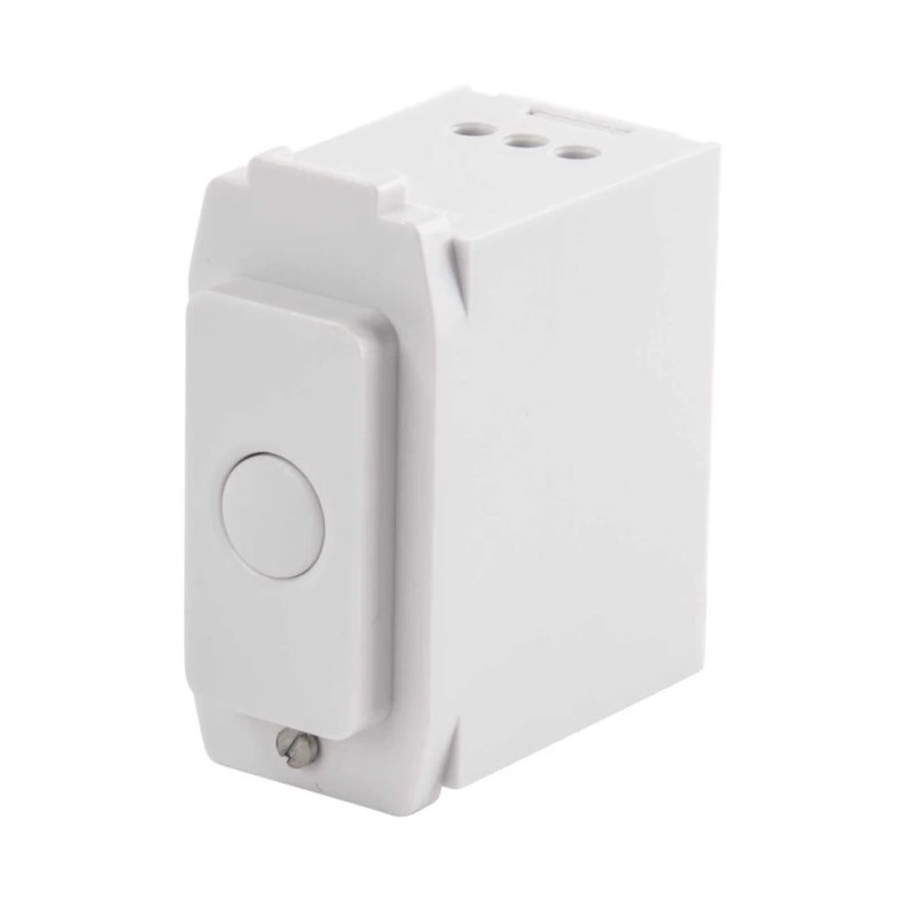
DANLERS GRTLA MK ILM Instalação - Página 2
Procurar online ou descarregar pdf Instalação para Interruptor DANLERS GRTLA MK ILM. DANLERS GRTLA MK ILM 2 páginas. Grid time lag switches (3-wire versions)
Também para DANLERS GRTLA MK ILM: Notas de instalação (2 páginas)

Installation Procedure
1. Please read these notes carefully before commencing work.
In case of doubt please consult a qualified electrician.
Make sure the power is isolated from the circuit.
2. The grid time lag switch (3-wire version) should be connected as:
L
Live
N
Neutral
SL
Switched Line output
3. Existing two-way strapper lines can usually be used to wire these
devices in parallel, as shown in the wiring diagrams opposite.
4. The time lag is adjusted via a spindle located on the bottom edge of
the device, as shown below.
5. When wiring has been completed and verified, switch on supply and
test operation.
A PPROXIMATE
SETTINGS
1 hour
1
2
min
hours
TIME
Typical wiring diagrams
1-way grid time lag (3-wire version)
L
L
N
230 VAC
N
Example of a typical 2-way circuit
Multi-way grid time lag (3-wire version) in parallel
L
SL
SL
L
N
N
Grid time lag
Grid time lag
3-wire version
3-wire version
V
Grid time lag
3-wire version
Optional CAPLOAD,
Power factor
load
correction capacitor.
See fault finding.
load
N
L
230 VAC
L
SL
N
Grid time lag
SL
3-wire version
load
N
L
230 VAC
