aevit SMART-SHIFT Manual de instalação - Página 13
Procurar online ou descarregar pdf Manual de instalação para Acessórios para automóveis aevit SMART-SHIFT. aevit SMART-SHIFT 16 páginas.

OTHER APPLICATIONS
If your particular vehicle uses a cable operated shift mechanism, or a mechanical "rod style", one of the bracket
kits can likely be modified to fit your application, or you can fabricate your own. The actuator has a total stroke
of 2-1/4". You must weld or bolt a bracket to the shift arm on the transmission such that the arc of travel from
Park to Low gear is approximately 2-1/4". This will be the connection point of the actuator. Other optional
mounting techniques could involve purchasing a Ford or Chrysler shift cable and adapting it to your particular
vehicle. You could also mount the actuator inside the vehicle with this sort of cable control. Feel free to contact
EMC Service with your particular applications should you encounter installation problems.
2.3 MOUNTING THE CONTROLLER AND TOUCHPAD
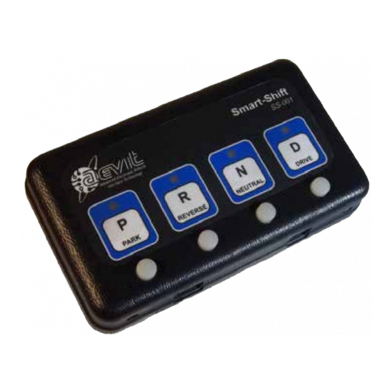
The remaining modules - Controller Module and Touchpad - will be located inside the cabin of the vehicle.
The Controller Module can be attached under the dash in a convenient location, provided it is within reach of
the actuator harness and the electrical connections described in the next section. Avoid locating the module
next to a heat source.
The Touchpad will be mounted according to the users range of motion, needs or preference. On back of the
Touchpad you will find (2) 1/4-20 threaded studs to help facilitate attaching the Touchpad to something suit-
able.
2.4 ELECTRICAL CONNECTIONS
IMPORTANT NOTE: DO NOT CUT THE CONNECTOR END OFF OF THE ACTUATOR TO ROUTE YOUR
CABLE AS IT IS A SPECIAL SHIELDED,TWISTED PAIR CABLE WITH THREE BLACK WIRES.
There is only (1) harness that will interface with the vehicle. The other connections are the telco cord from the
touchpad to the controller and the actuator connector to the controller. If you are routing the actuator cable
through the floorboard of the vehicle, DO NOT cut the connector off of the harness. This connector contains
shielded twisted pairs with three black wires. If this cable is cut and wired back incorrectly, damage to the
actuator will result which is not covered under warranty. Make sure you drill a large enough hole to accommo-
date the connector.
Locate the power cable which plugs into the Smart-Shift Harness port and connect the four wires as depicted
and explained in FIGURE 2.
RED - Connect to 12V dc source, through a 15 AMP circuit breaker that is hot only with the ignition of the
vehicle On.
BLACK - Connect to Chassis Ground.
WHITE - Connect to the brake light switch wire that has 12V dc only when the brake lights are "On". The Smart-
Shift will not work if this wire is not connected to a brake light feed.
GREEN - Connect to a wire that supplies the dash lamp with 12V dc when the dash lights are "On". This wire
provides backlight illumination to the touchpad.
11
SMART-SHIFT INSTALLATION
