Dantherm NF-8HD Manual - Página 4
Procurar online ou descarregar pdf Manual para Controlador Dantherm NF-8HD. Dantherm NF-8HD 20 páginas.

01AUG 1005GB
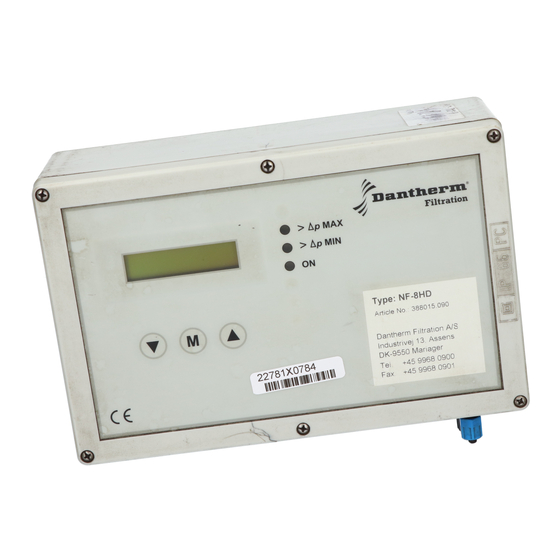
INSTRUCTIONS for installing filter control systems NF-8HD and NF-16HD
Safety Precautions.
In order to ensure work safety, the following precautionary measures are recommended in ad-
dition to those usually stipulated for operations on electrical installations:
• Installation of control systems may only be undertaken by professional personnel, accord-
ing to the standards for electrical materials.
• At the installation site, all the conventional rules, stipulations, precautions and instruc-
tions for electrical installation must be observed.
• Adjustment of electrical controllers with the casing removed may only be carried out by
specialised personnel and in full accordance with the stipulated safety rules.
• In the mains supply, 230 V AC is applied to the terminals L230 (1) and N (3) (Fig. 5, 3.1).
For the 110V AC supply the terminals L110 (2) and N (3) are to be used (or the special
voltage ordered in conformity with the label and terminal specification).
In addition the safety recommendation NF10 must be observed.
General.
The filter control system NF-8HD / NF-16HD is an electrical controller for control of filter
plants with pressure pulse air cleaning using 24V DC magnetic coils at the valves.
When the voltage supply is turned on, the filter control automatically operates for previously
specified cleaning periods without any need of external intervention.
The filter controllers NF-8HD / NF-16HD have a differential pressure transmitter built-in.
The filter control system is enclosed in an electrical box with an IP65 safety classification.
The filter controllers are suitable for outdoor installation and can be installed directly on the
pressure vessel (with installation mountings).
The control system is entirely assembled and tested.
Connection.
The filter control system NF-8HD is mounted right in front of the first 8 valves. If more than
8 valves are present, an NF-8E expansion unit is mounted immediately in front of the next 8
valves or a NF-16HD can be used. There may be up to 9 NF-8E / NF-16E expansion units at-
tached to the main control NF-8HD / NF-16HD. Where there are more than 160 valves in the
filter, several NF-8HD / NF-16HD and NF-8E systems must be used.
After the control boxes have been set up, the valves can be attached to the terminals V1, + to
V8, + (at NF-8HD) or to V16, + (at NF-16HD).
Subsequently, in the case where NF-8E is used, the electrical controllers can be interlinked as
shown in Fig. 7. (WARNING ! No bridge may be connected to the output terminals of the last
unit, the terminals remain open).
Cat.20 / Tab. 05.91 / Page 05.01
