Siting and mounting the duct smoke detector
1. To minimise the impact of air turbulence and stratifi cation on
performance a duct smoke detector should be located as far as
possible downstream from any obstruction (ie, defl ector plates,
elbows, dampers, etc). In all situations confi rmation of velocity and
pressure differential within specifi cations is required.
A uniform non-turbulent (laminar) airfl ow between 0.5 and
20m/s must be present in the air duct. The pressure differential
between inlet (high pressure) and exhaust (low pressure) tubes
should be between 0.025 and 3mbar.
2. Locate the detector so that it is easy to view and service it.
3. If installing the detector in the return air side of the duct, locate
it at a point where it will not be diluted with outside air.
4. If detectors are fi tted downstream of fi lters the fi lters should
be kept clean. If they are blocked with dirt the duct smoke
detector will not function properly.
5. If possible, install duct smoke detectors upstream of air
humidifi ers and downstream of dehumidifi ers.
6. To minimise false alarms avoid mounting the detector in areas
of extreme high or low temperatures, in areas of high humidity
or in areas containing gases or high amounts of dust.
7. Remove the paper backing from the mounting template
supplied with the detector and fi x the template to the air duct
at the chosen location. Using the template as a guide drill two
mounting holes 2.5mm diameter for the two 6x12mm screws
supplied in the installation kit.
8. Drill 32mm holes for the sampling tubes, again using the
template as a guide. De-burr all holes.
9. Mount the detector housing to the air duct and fi x with the
two 6x12mm screws. Install the inlet tube, making sure the
holes face the air fl ow. The end of the inlet tube may need to
be supported as described in the section 'Sampling Tubes'.
Tighten the latch screw to secure the tube.
Wiring the duct smoke detector
Connect the line or loop wires as shown in the diagrams below.
CONVENTIONAL DUCT
SMOKE DETECTOR
SCREEN
SCREEN
R–
REMOTE LED
R+
L+ IN
L+ OUT
L– IN
L– OUT
N/O
N/C
COM
Fig 1. Wiring diagram for Conventional Duct Smoke Detectors
If a diode is to be fi tted for detector head removal, it should be
connected across L+ IN and L+ OUT.
+
–
VOLT-
}
FREE
RELAY
CONTACTS
FOR USE
AS
REQUIRED
+
–
ANALOGUE ADDRESSABLE
DUCT SMOKE DETECTOR
REMOTE LED
© Apollo Fire Detectors Limited 2004/JDR
Fig 2. Wiring diagram for Analogue Addressable Duct Smoke Detector
Fitting the detector head
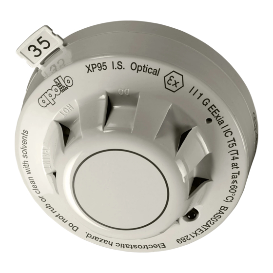
Duct smoke detector part no 53546-021 is designed to accept a
Series 65 head. The following heads may be used:
Series 65
Series 65 with fl ashing LED
Duct smoke detector part no 53546-023 is designed to accept an
Orbis head. The following head may be used:
Orbis
Duct smoke detector part no 53546-022 is designed to accept an
analogue detector head. The following heads may be used:
XP95
Discovery
For address details see section 'Address setting'overleaf
After fi tting the detector head fi t the baffl e. Locate the edge of the
baffl e in the slots in the side wall of the housing.
Functional test
When the detector head has been fi tted a test should be carried
out using smoke test gas part no 29600-225. Insert the test gas nozzle
into the test point on the unit cover. Press can against cover to
release gas into chamber. Caution: do not spray gas for more than
½ second .
After 15–20 seconds a conventional detector head should change
to the alarm state and an analogue detector should transmit an
analogue value of 55 or greater. In both cases the detector LED
should illuminate. Allow time for the gas to disperse before resetting
the detector.
Address setting
If duct detector 53546-022 is used the address of the detector must
be set before fi tting the detector head. The address of the detector
is set using the XPERT card. The address settings are shown in the
diagram overleaf.
+
–
SCREEN
SCREEN
–R
+R
L2
L2
L1
L1
+
–
Ionisation smoke
Optical smoke
55000-217
55000-317
55000-216
55000-316
Optical smoke
ORB-OP-12001-APO
Ionisation smoke
Optical smoke
55000-500, 520
55000-600, 620
58000-500
58000-600

