Datakom DKG-117 Manual do utilizador - Página 6
Procurar online ou descarregar pdf Manual do utilizador para Painel de controlo Datakom DKG-117. Datakom DKG-117 12 páginas. Synchroscope and check synch relay
Também para Datakom DKG-117: Manual do utilizador (12 páginas)

DKG-117 User Manual
3. DISPLAYS
3.1 Led Displays
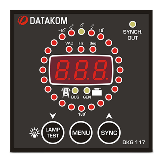
The unit has 30 LEDs, divided in 4 groups:
-Group_1: Synchronoscope: this group indicates the instantenous phase angle of the genset
voltage with reference to the busbar voltage. When both networks are in synchronization, the upper center
yellow led with 0º mark will illuminate. When the genset frequency is higher then the busbar frequency, then
the synchroscope will turn in the clockwise direction. When the genset frequency is lower then the busbar
frequency, then the synchroscope will turn in the counter-clockwise direction.
-Group_2: Status: This group indicates the current status of the busbar and genset
voltages and the synchronization checking status.
-Group_3: SYNCH: This led will indicate the status of the SYNCH CHECK relay output.
-Group_4: Unit: This group indicates the unit of the value shown on the digital display.
Function
SYNCHROSCOPE
GENERATOR
BUS
SYNCHRONIZED
UNIT GROUP
Color
Red and Yellow
Yellow
Yellow
Yellow
Red
Description
When both busbar and genset voltages are within
programmed limits, the synchroscope will illuminate
automatically. Only one of the leds turns on at a time.
The led indicates the phase angle between the
busbar phase and the genset phase U.
If the right hand side of the graph is illuminated, this
means that the genset phase is leading (in advance)
the busbar.
If the left hand side of the graph is illuminated, this
means that the genset phase is lagging (in retard).
A clockwise scrolling of the led graph means that the
genset frequency is higher than the busbar
frequency.
A counter-clockwise scrolling of the led graph means
that the genset frequency is lower than the busbar
frequency.
The LED will turn off if the genset phase voltage is
outside the set limits.
It will flash when the genset phase voltage is within
the limits and the synchronization is not checked.
It turns on steadily when the synchronization is
checked.
The LED will turn on when the busbar voltage is
within the limits.
The LED will turn on when the CHECK SYNCH relay
is energized.
The synchronization checking may be initiated or
terminated either manually by depressing the SYNCH
pushbutton or with the SYNCHRONIZATION CHECK
ENABLE signal input.
This group indicates the unit of the value displayed in
the digital display. Different values may be scrolled by
pressing the MENU key.
V-01
(24.03.2014)
- 6 -
