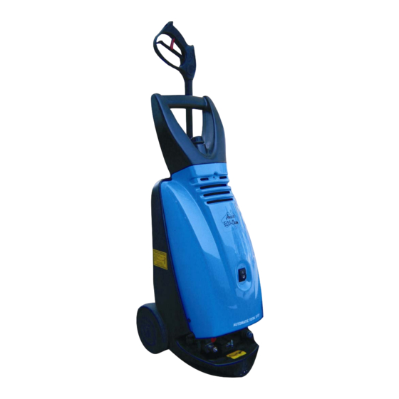
Aussie Concept F140 Manual de instruções - Página 7
Procurar online ou descarregar pdf Manual de instruções para Máquina de lavar roupa de pressão Aussie Concept F140. Aussie Concept F140 13 páginas. Domestic cold water high pressure cleaner

ASSEMBLY/PREPARATION & USE
WARNING: When the machine is new it requires a brief running in of motor/pump unit.
Running in consists of running the machine for no longer than one hour and letting it cool for at
least one hour. This operation should be repeated at least three or four times.
Step 1: -
Remove plastic travel caps from both inlet and outlet (if supplied).
-
Fit inlet and outlet hoses as described below.
Step 2: -
Connect water hose (garden hose). (Ensure fittings are clean.)
-
Provided with your machine is a hose adaptor which allows Item
No. 1 to connect onto Item No. 2 as illustrated.
-
Item No. 2 also comes complete with a mesh filter as standard.
-
If you do not receive the mesh filter inside the hose connector, do not operate
machine as this filter protects the pump against debris entering into the system.
-
Push inlet hose (1) onto hose connector (2):
Step 3: -
Connect high pressure hose to pump outlet.
-
Insert high pressure hose into machine outlet as pictured (1)
-
Tighten union nut (black coupling) by hand (2).
-
Turn on water
Step 4: -
Tighten, using a 22mm spanner, the high pressure hose onto the F140 gun. We
recommend Teflon tape is used between gun and hose to avoid leaks.
Please Note: If there are any leaks on the high pressure accessories, including hose,
gun and lances, this can cause the Total Stop function on your pressure cleaner to not
operate correctly.
ACCESSORIES MUST BE REPLACED IMMEDIATELY.
Assembly of spray attachment for Concept F140
-
Screw, by hand, the vario
nozzle (1) or turbo nozzle (2)
into the high pressure gun (3)
until black coupling is tight.
IMPORTANT: The machine must only be operated in an upright
position.
Any leaks will cause the machine to pulsate.
Concept F140 Cold Water Pressure Cleaners – March 09
1
2
Fig. 2
Fig. 3
LEAKING
3
Fig. 4
Page 7 of 12
