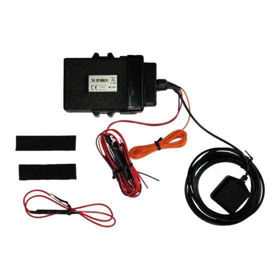
Datatool TrakKING ST61 Manual de instalação - Página 4
Procurar online ou descarregar pdf Manual de instalação para GPS Datatool TrakKING ST61. Datatool TrakKING ST61 6 páginas.

Step 1: Unit Installation
Careful consideration should be given to where the main TrakKING Control Unit will
be fitted. Ensure that the unit is fitted in a covert position, this means behind panels
that are permanently fixed and ideally not directly under a seat which is easily
accessible.
Typical locations include under the fuel tank, under a bolted on side panel or behind a
fairing panel. The unit should be secured using cable ties and it is imperative that the
provided self-adhesive rubber pads are used to protect the unit from vibration.
The ST61 has LED service lights under the translucent cap. During commissioning it
may be required to view the status of these LEDs therefore do not refit bodywork until
the unit has successfully installed.
Step 2: GPS Antenna
A suitable location point is required for the mounting of the GPS antenna, this must be
covert and out of sight and the antenna must be mounted using the self-adhesive pad.
The GPS antenna should be mounted with the top of the antenna facing upwards (the
self-adhesive pad being on the bottom of the antenna) and the antenna must not be
shielded by metal or carbon fibre. Suggested possible locations include under the rear
seat, inside a side panel or under a fairing panel.
The antenna wiring harness should be securely fastened by cable ties wherever
possible and the wiring routed in a way which makes it as discreet as possible.
The position of the GPS antenna must have a good and clear 'view of the sky'.
Please Note:
The antenna wiring is a shielded cable that cannot be cut to be shortened
or extended. Any excess cable should be coiled neatly and cable tied in place to avoid
damage.
Step 3: Permanent Ground Connection (Black Wire)
This should be as close to the unit as possible. If possible do not share the earth
directly with any other system but instead use a direct earth point. If the vehicle is fitted
with a radio or intercom system do not connect to any circuits related to this to avoid
causing interference. Do not connect direct to the vehicle battery.
Step 4: Switched 12v Connection (Orange Wire)
Locate a suitable 12v ignition supply that remains 12v whilst cranking the engine. Iot
is recommended to use a circuit protected by a maximum 10amp fuse, if no suitable
fused circuit is available fit an inline fuse of 3 amp capacity. Connect the TrakKING
orange wire to this ignition supply using soldered connections and insulate.
It is imperative that the ST61 has a good 12v ignition power feed that stays live at all
times the ignition is switched
on.
CONFIDENTIAL
4
Scorpion Automotive Ltd. Scorpion House, Drumhead Road, Chorley North Business Park, Chorley, Lancashire PR6 7DE
01257 249928
www.trakking.net
Rev: 160527 DP
