Bender FP200W Manual de início rápido - Página 6
Procurar online ou descarregar pdf Manual de início rápido para Monitor Bender FP200W. Bender FP200W 12 páginas. Front panel for isometer® iso685-s variants
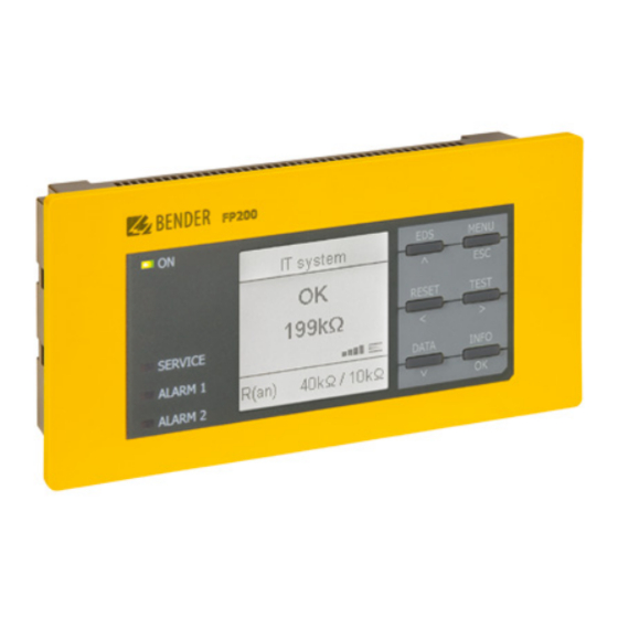
Frontpanel FP200(W)
1. Schneiden Sie einen passenden Ausschnitt für das
FP200 in Ihrem Schaltschrank aus.
2. Schieben Sie das FP200 in den Ausschnitt.
3. Montieren Sie die beiliegenden Schraubbefestigungen
von hinten an das Gehäuse. Drehen Sie die Schrauben
mit einem Schraubendreher fest, so dass das FP200 an
der Frontplatte fest sitzt.
4. Stecken Sie einen der beiden RJ45-Stecker des
Patchkabels in die dafür vorgesehene REMOTE-Buchse
auf der Rückseite des FP200. Stecken Sie den anderen
RJ45-Stecker des Patchkabels in die REMOTE-Buchse
auf der Vorderseite der ISOMETER® iso685-S Variante.
i
Das mitgelieferte Patchkabel ist für einen Temperatur-
bereich von 0...60 °C spezifiziert, während das
FP200(W) für den Bereich -40...+70 °C zugelassen ist.
Möglichkeit 2:
Montage des ISOMETER® iso685-S-x-Gerätes direkt am
Frontpanel FP200(W). Verbindung via BB-Bus.
2.1
2.5
6
FP200_D00169_04_Q_INTE/06.2021
1. In the cabinet, cut out a section large enough for the
FP200 front panel to slide in.
2. Place the FP200 into the cutout.
3. Insert the enclosed screw fasteners from behind the
enclosure. Tighten the screws with a screwdriver so
that the the FP200 is secured on the front panel.
4. Insert one of the patch cable RJ45 connectors into the
REMOTE socket on the back of the FP200. Insert the ot-
her RJ45 connector into the REMOTE socket on the
front of the ISOMETER® iso685-S variant.
i
The patch cable supplied is specified for a temperature
range of 0...60 °C while the FP200(W) has been appro-
ved for the range -40...+70 °C.
Option 2:
Mounting of the ISOMETER® iso685-S-x device directly on
the FP200(W) front panel. Connection via BB bus.
2.2
2.6