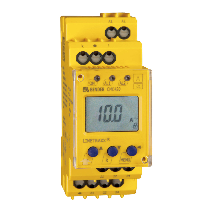
Bender cme420 Boletim de instalação - Página 2
Procurar online ou descarregar pdf Boletim de instalação para Relés Bender cme420. Bender cme420 2 páginas.

Figure 4 - Setting alarm type and CT ratio (if used)
The recommended first step is to set the type of alarm that will be used. Set this option to "HI"
for undercurrent, "LO" for undercurrent, or "In" for both.
If a current transformer is being used, the ratio must be changed as well, in order to be able
to program correct values seen on the primary (no calculations are required when setting trip
values after this step is completed). Note that while an X/5 ratio CT is required for use with this
device, the ratio is entered in as if it were an X/1. For example, if a 50:5 CT is being used, enter
a value of "10" for the CT ratio value.
If the device is being directly connected to the system, leave the ratio set to 1.
> 1.5 sec
x 3
R
< 1.5 sec
< 1.5 sec
Press nothing for
overcurrent (HI)
otherwise:
R
1x for both (In)
2x for undercurrent (Lo)
< 1.5 sec
Figure 5 - Setting Alarm Values
The CME420 has two alarm values that may be set. Use the following guidelines for setting
these numbers:
•
Using only overcurrent OR undercurrent: Only one value is required. The value I
explicit alarm value that is set. The value I
vated, which is a percentage value based on the previously set trip value.
•
Using both overcurrent AND undercurrent: Both values are required. The value I
overcurrent value, entered as an explicit number. The value I
entered as a percentage of the previously entered overcurrent value. EXAMPLE: For an
overcurrent alarm of 20 A and an undercurrent alarm of 10 A, enter "20" for I
"50%" for I
.
1
> 1.5 sec
< 1.5 sec
< 1.5 sec
T
R
Setpoint
Adjustment
< 1.5 sec
R
Bender Inc. • USA: 800.356.4266 / 610.383.9200 / [email protected] • Canada: 800.243.2438 / 905.602.9990 / [email protected] • www.bender.org
T M
> 1.5 sec
x 2
To quit
> 1.5 sec
OR
To set CT
ratio
R
> 1.5 sec
= Flashing Symbol
T
R
Ratio Adjustment
> 1.5 sec
x 2
To quit
> 1.5 sec
is an optional prewarning that may be acti-
1
is the undercurrent value,
1
< 1.5 sec
T
R
Setpoint
Adjustment
< 1.5 sec
> 1.5 sec
> 1.5 sec
= Flashing Symbol
Figure 5 - Changing Time Delays
Four separate time delays are available:
•
t
- Response delay, prewarning
on1
•
t
- Response delay, main alarm
on2
Figure 6 - Latching behavior (fault memory)
Changing this setting to "ON" will cause the CME420 to latch in the event of an alarm, and re-
quire a manual reset if the alarm clears. Changing this setting to "OFF" will cause the CME420
to automatically reset if the alarm clears.
is the
2
is the
2
, and enter
2
Figure 7 - Contact operation
Use this option to change the behavior of the contacts between normally deenergized (non-
failsafe) mode and normally energized (failsafe) mode. The two SPDT contacts may be changed
individually. Note that the CME420 labels normally deenergized operation as "N/O" and nor-
mally energized operation as "N/C"; utilzing a normally open or normally closed contact only
depends on which contact output is wired.
Installation Bulletin / Reference Guide
•
t - Startup delay
•
t
- Delay on release
off
T
R
t
1 Adjustment
on
> 1.5 sec
0...10 seconds
R
< 1.5 sec
Press Twice
> 1.5 sec
< 1.5 sec
R
> 1.5 sec
Press:
1 x for t
2
on
2 x for t
0...10 sec
3 x for t
off
0...99 sec
OR
= Flashing Symbol
< 1.5 sec
> 1.5 sec
< 1.5 sec
R
Press Once
> 1.5 sec
< 1.5 sec
> 1.5 sec
< 1.5 sec
= Flashing Symbol
T
R
Fault Memory
ON/OFF Select
T
R
Failsafe
> 1.5 sec
ON/OFF Select
R
< 1.5 sec
Press Once
> 1.5 sec
< 1.5 sec
R
> 1.5 sec
Press Once
= Flashing Symbol
< 1.5 sec
Document NAE1038030 • 10.2012 • © Bender Inc. • Page 1/1 • Side 2/2
CME420
