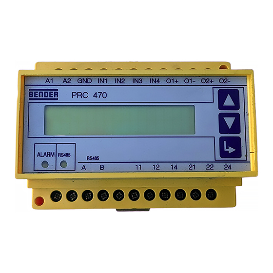
Bender PRC470 Series Manual - Página 12
Procurar online ou descarregar pdf Manual para Controlador Bender PRC470 Series. Bender PRC470 Series 20 páginas. Control and indicating device for ems and eds systems

PRC470, PRC470E
Ist ein Fehler vorhanden, so wird dies angezeigt.
position (menü:
)
adr: 2k3
Um den aktuellen Messwert anzuzeigen, muss die
Memory-Funktion (m7) ausgeschaltet werden.
off
Messstromwandler ist ausgeschaltet
An Messstromwandlereingang ist kein Messstromwandler
angeschlossen oder die Wandleranschlussleitung ist unter-
brochen.
Am Messstromwandlereingang besteht ein Kurzschluss.
Drücken Sie die Taste
um das Menü zu verlassen.
m6: relais
Das Menü „m6: relais" dient der Einstellung der Arbeitsweise der
Alarmrelais für alle an den BMS-Bus angeschlossenen Auswerte-
geräte RCMS470-12 bzw. EDS47x-12.
Berücksichtigen Sie bei Änderung der Arbeitsweise
der Alarmrelais das neue Verhalten der Kontakte.
Werden Kontakte beispielsweise zur Anschaltung
von Warnleuchten oder Hupen oder gar zur Einlei-
tung von Schaltvorgängen benutzt, so sind Umver-
drahtungen in der Kontaktverschaltung notwendig.
Rufen Sie das Menü „m6: relais" mit der Taste
m6: relais
( )
↓
↑
(m5:
, m7:
)
Wählen Sie mit den Pfeiltasten die Arbeitsweise der Alarmrelais.
nc 12
14
( )
↑
(no 12
14:
)
no
Arbeitsstrom. Das Alarmrelais ist im Gutzustand des Gerätes abgefallen
und zieht im Fehlerfall an.
nc
Ruhestrom. Das Alarmrelais ist im Gutzustand des Gerätes angezogen und
fällt im Fehlerfall ab.
Drücken Sie die Taste
um das Menü zu verlassen.
m7: memory
Das Menü „m7: memory" dient der Einstellung des Verhaltens des
Fehlerspeichers für alle an den BMS-Bus angeschlossenen Aus-
wertegeräte RCMS470-12 bzw. EDS47x-12.
m7: memory
( )
↓
↑
(m6:
, m8:
)
Drücken Sie
um in das Untermenü zu gelangen.
memory on
( )
↑
(off:
)
12
Any faults will be indicated.
position (menü:
adr: 2k3
off
Press the
m6: relay
The "m6: relay" menu is used to set the operation of the alarm re-
lays for all evaluators RCMS470-12 or EDS47x-12 that are connect-
ed to the BMS bus.
Open the "m6: relay" menu with the
auf.
Using the arrow keys, select the operation of the alarm relays.
nc 12
no
nc
Press the
m7: memory
The "m7: memory" is used to set the behaviour of the fault mem-
ory for all evaluators RCMS470-12 or EDS47x-12 that are connect-
ed to the BMS bus.
m7: memory
Press the
memory on
)
The Memory function (m7) must be deactivated if you
wish to display the present measurement value.
The measuring current transformer is switched off
No measuring current transformer is connected to the
measuring current transformer input or the connection line
for the transformer is interrupted.
There is a short-circuit at the measuring current transformer
input.
key to exit the menu.
Please note that the behaviour of the contacts will
change if the operation of the alarm relays is
changed. If, for example, contacts are to be used to
connect warning lights or horns or even to trigger
switching operations, it will be necessary to change
the wiring in the contact circuit.
m6: relais
( )
↓
↑
(m5:
, m7:
)
14
( )
↑
(no 12
14:
)
N/O operation. The alarm relay has dropped off to the acceptance state of
the device and will pick up in the event of a fault.
N/C operation. The alarm relay has picked up to the acceptance state of the
device and will drop off in the event of a fault.
key to exit the menu.
( )
↓
↑
(m6:
, m8:
)
key to open the submenu.
( )
↑
(off:
)
key.
108001 / 11.2004
