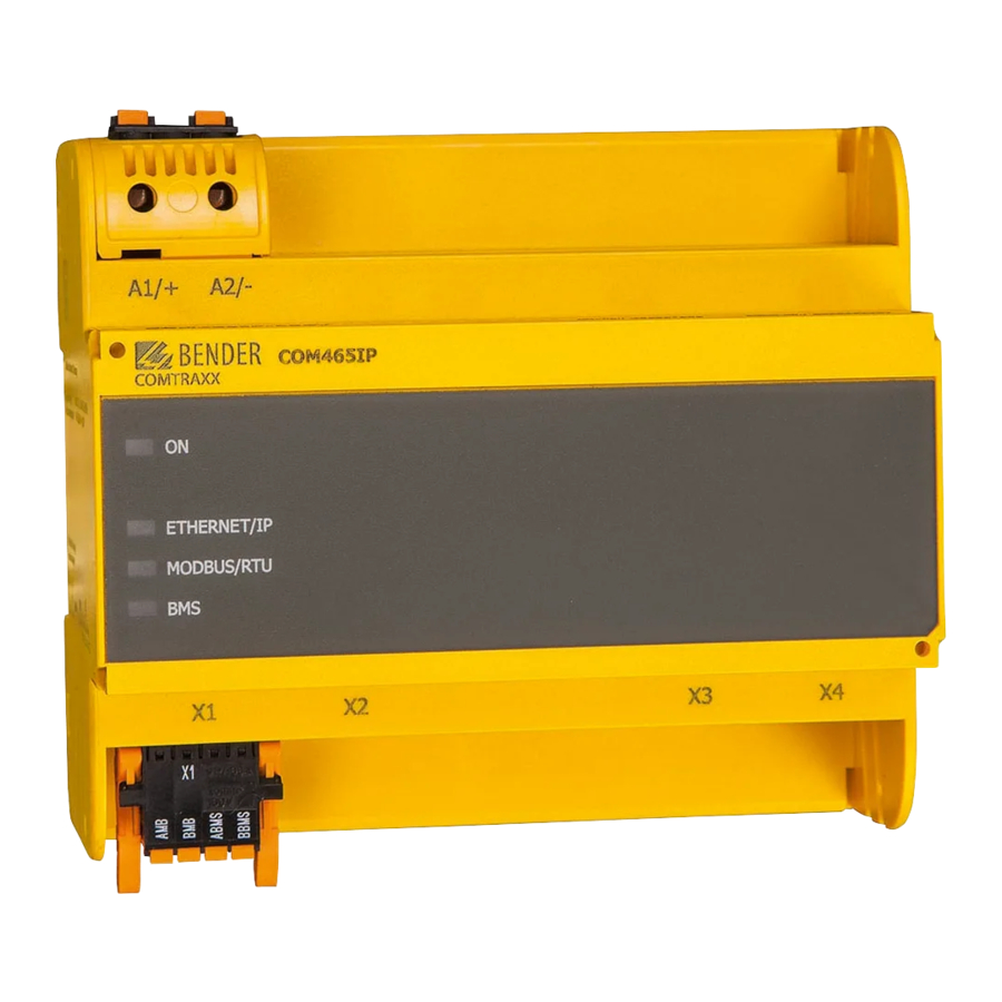
Bender COMTRAXX B95061065 Manual de início rápido - Página 4
Procurar online ou descarregar pdf Manual de início rápido para Porta de entrada Bender COMTRAXX B95061065. Bender COMTRAXX B95061065 8 páginas. Condition monitor with integrated gateway

COMTRAXX® COM465IP/COM465DP
Gerät anschließen
1
A1/+
A2/-
COMTRAXX
ON
PROFIBUS
ETHERNET/IP
MODBUS/RTU
BMS
X1
X1
3
4
Spannungsversorgung (siehe Typenschild)
Anschluss PROFIBUS DP (nur COM465DP)
Schnittstelle Modbus RTU: Klemmen AMB und BMB
BMS-Bus (Bender-Messgeräte-Schnittstelle):
Klemmen ABMS und BBMS
Ethernet-Anschluss (RJ45) zum Anschluss an das
PC-Netzwerk sowie an BCOM
Schalter Abschlusswiderstand Modbus RTU
Schalter Abschlusswiderstand BMS-Bus
Micro-USB-Schnittstelle (z. Zt. ohne Funktion)
Mini-HDMI-Schnittstelle (z. Zt. ohne Funktion)
1. Klemmenabdeckungen des Geräts entfernen
2. Bus-Anschluss:
– BMS
Verbinden Sie die Klemmen ABMS und BBMS (4) mit
dem BMS-Bus (A auf A, B auf B). Befindet sich das
COM465...P an einem Ende des BMS-Busses, so müs-
sen Sie den Terminierungsschalter des Gerätes (7)
auf „ON" schalten.
– Modbus RTU
Verbinden Sie die Klemmen AMB und BMB (3) mit
dem Modbus RTU (A auf A, B auf B). Befindet sich das
COM465...P an einem Ende des Busses, so müssen
Sie den Terminierungsschalter des Gerätes (6) auf
„ON" schalten.
– Ethernet (BCOM, Modbus TCP, SNMP)
Ethernet-Kabel (RJ45) in das COM465...P einstecken
(5) und mit Netzwerk verbinden. Es wird empfohlen,
mindestens ein Ethernet-Kabel der Kategorie 5
(Cat. 5) zu verwenden.
4
COM465xP_D00216_02_Q_DEEN/07.2021
COM465DP
COM465IP
PROFIBUS DP
X2
Stecker X1
Stecker X2
Stecker X3
Stecker X4
X3
X4
2
5
Power supply (see nameplate)
1
PROFIBUS DP connection (COM465DP only)
2
Modbus/RTU interface: Terminals AMB and BMB
3
BMS bus (Bender measuring device interface):
4
Terminals ABMS and BBMS
Ethernet connection (RJ45) for the connection
5
to the PC network as well as to BCOM
Modbus RTU terminating resistor switch
6
BMS bus terminating resistor switch
7
Micro-USB interface (currently has no function)
8
Mini-HDMI interface (currently has no function
9
1. Remove terminal covers of the device
2. Bus connection:
– BMS
Connect the terminals ABMS and BBMS (4) to the
BMS bus (A to A, B to B). If the COM465...P is at the
end of the BMS bus, you must switch the terminating
switch on the device (7) to „ON".
– Modbus RTU
Connect the terminals AMB and BMB (3) to the
Modbus RTU (A to A, B to B). If the COM465...P is at
the end of the bus, you must switch the terminating
switch on the device (6) to „ON".
– Ethernet (BCOM, Modbus TCP, SNMP)
Connect Ethernet cable (RJ45) to the COM465...P (5)
and connect to the network. It is recommended to
use at least on Ethernet cable of category 5 (Cat. 5).
Connecting the device
OFF
R
ON
OFF
R
ON
MB
BMS
6
7
8
9
Plug X1
Plug X2
Plug X3
Plug X4
