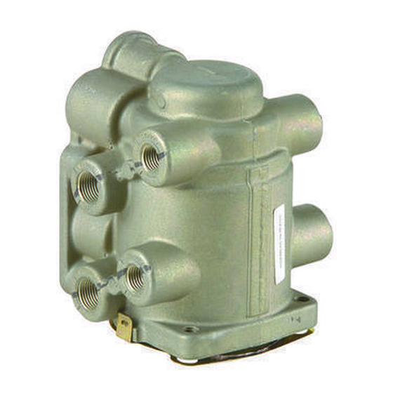
BENDIX E-7 DUAL BRAKE VALVE Manual - Página 4
Procurar online ou descarregar pdf Manual para Unidade de controlo BENDIX E-7 DUAL BRAKE VALVE. BENDIX E-7 DUAL BRAKE VALVE 9 páginas. Dual brake valve

LEAKAGE CHECK
1. Make and hold full brake application.
2. Coat the exhaust port and body of the brake valve with
soap solution.
3. Leakage not to exceed a 1" bubble in 3 seconds in both
the applied and released position.
If the brake valve does not function as described above or
leakage is excessive, it is recommended that it be replaced
with a genuine Bendix new or remanufactured unit, available
at your local authorized Bendix parts outlet.
REMOVAL (IF NECESSARY)
1. Block the wheels or hold the vehicle by means other
than air brakes and exhaust air pressure from reservoirs
supplying air to the E-7
2. In most installations, the E-7
removed and replaced by removing the three cap screws
which hold the pedal assembly in place and removing
the pedal assembly. The internal parts may then be
removed from the E-7
3. If necessary to remove the E-7
compartment bulkhead, identify the two supply and two
delivery lines to their respective ports as connected to
the brake valve. There may also be air lines to other
brake devices inside the cab, which should be properly
identified before disconnecting. In the case of a manifold
type installation, the three cap screws which hold the
manifold to the brake valve may be removed and the
brake valve removed.
DISASSEMBLY (REFER TO FIGURE 2)
1. Remove retainer, (18). Remove the lower static piston
assembly.
2. Fashion a hook from a piece of wire and insert hook
through inlet-exhaust valve of upper static piston
assembly. Pull firmly and remove upper static piston
assembly.
DISASSEMBLY (UPPER STATIC PISTON
ASSEMBLY)
1. Remove o-rings (2) and (3).
2. Remove retaining ring (17), and remove secondary circuit
inlet exhaust assembly (1).
DISASSEMBLY OF LOWER STATIC ASSEMBLY
1. Apply firm pressure on spring seat (19), which will
compress piston return spring. Locking groove in piston
is now accessible through rectangular opening in lower
static piston body. Insert wire or screwdriver into locking
groove, thus holding static piston spring in compressed
position.
4
™
valve.
™
internal parts may be
™
as described in disassembly.
™
from the engine
2. Insert blade of screwdriver through relay piston exhaust
passage into slot of stem, and remove lock nut (14),
being careful not to nick the exhaust seat of the relay
piston.
3. Remove spring seat (15), stem spring (23), spring seat
nut (16), rubber spring seat (19), and rubber spring, (10).
4. Relay piston, relay spring, (5) and stem bolt may now
be removed.
5. Removal of screwdriver or wire from locking groove will
permit spring load to push the primary circuit piston from
the lower static piston. Note: Care should be used when
removing tool from locking ring because of spring load.
6. Remove o-rings (6 & 7) from relay piston and o-ring, (9)
from primary circuit piston.
7. Remove o-rings (11 & 12) from lower static piston.
8. Remove large retaining ring (20) from lower static piston,
and remove primary circuit inlet/exhaust valve assembly
(4).
DISASSEMBLY-EXHAUST CHECK VALVE
Some E-7
™
brake valves have an air exhaust check valve
(13, 21 & 22) as shown on Figure 2. If so, remove screw
(21), and washer (22), and discard diaphragm (13). Replace
(21) and (22) using new diaphragm (13).
ASSEMBLY
Note: Before assembly, lubricate all o-rings, bores, and
mating surfaces with silicone lubricant, pc. no. 291126 (Dow
Corning 55-M). Do not lubricate rubber spring.
1. Install secondary circuit inlet-exhaust assembly (1) in
upper static piston, making certain retaining ring (17) is
engaged in groove of upper static piston bore.
2. Install o-rings (2 & 3) on upper static piston and install in
valve body.
3. Install primary circuit inlet-exhaust assembly in lower
static piston making certain retaining ring (20) is engaged
in groove of lower static piston bore.
4. Install three o-rings (2 of 11), and (12) in grooves of lower
static piston assembly. (Note: The larger diameter
o-ring is installed in groove nearest to bottom of piston
assembly.)
5. Install o-rings (6) and (7) on relay piston and o-ring (9)
on primary circuit piston.
6. Carefully clamp primary circuit piston in a soft-jawed
vise taking care not to damage the exhaust seat or the
outside diameter. Assemble the rubber spring, (10) over
the center stem of the center of the piston, then the
spring seat (19) and the spring seat nut (16). Tighten
the spring seat nut until the end of the piston stem and
the spring seat nut are flush.
