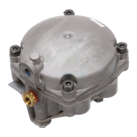
BENDIX RE-6NC Manual - Página 8
Procurar online ou descarregar pdf Manual para Unidade de controlo BENDIX RE-6NC. BENDIX RE-6NC 13 páginas. Relay valves

7. Remove and discard o-ring(7) from under the crimped-
on retaining ring located in the upper portion of the valve
body.
8. Turn the valve over, holding the exhaust cover, remove
the 3 cap screws(27) from the exhaust cover(22).
Remove the spring(20) and set the cap screws and
spring aside for the assembly process.
9. Remove and discard the small o-ring(19) from the
exhaust cover (located on the check valve post).
10. The RE-6NC
™
valve will not have a check valve(17)
and spring(18).
11. Remove and discard the check valve (17) and spring(18)
in the RE-6
™
valve.
12. Remove and discard the diaphragm(23) from the
exhaust cover. Set screw(25) and washer(24) aside
for the assembly process.
13. Remove the emergency piston(9) and inlet / exhaust
valve(10) assembly by pushing the assembly through
the valve body, from the relay piston side of the valve.
The whole assembly will come out of the valve body
as one unit.
14. Remove and discard o-ring(8) located in the grove of
the emergency piston.
15. Remove and discard o-ring(21), which creates the
seal between the emergency piston and the exhaust
cover.
16. Remove valve retainer(16) with appropriate pliers and
set aside for the assembly process.
17. Remove and discard all internal parts. Valve guide(15),
o-rings(13&14), spring(12), valve retainer(11), inlet /
exhaust valve(10).
CLEANING & INSPECTION
1. Using mineral spirits or an equivalent solvent, clean and
thoroughly dry all metal parts. Do not damage bores
with metal tools.
2. Wash all non-metallic components in a soap and water
solution. Dry thoroughly.
3. Inspect interior and exterior of all metal parts for severe
corrosion, pitting, and cracks. Superfi cial corrosion
and/or pitting on the exterior of the body and cover is
acceptable. Replace the entire valve if the body or
cover interior show signs of corrosion or pitting.
4. Inspect each non-metallic component for cracks, wear,
or distortion. Replace the valve if these conditions are
found.
5. Make certain the air channel running from the cover
through the top surface of the body to the supply port
is clear and free of obstruction.
6. Inspect the pipe threads in the body. Make certain they
are clean and free of thread sealant.
7. Inspect all air line fi ttings for corrosion. Replace as
necessary. Remove all old thread sealant before
reuse.
8
ASSEMBLY
Before assembly, lubricate all o-rings, seals, and pistons as
well as body and cover bores, using the lubricant provided
in the maintenance kit. Use all of the lubricant, and spread
it evenly on the rubbing surfaces.
1. Install o-ring(8) into the grove on the emergency
piston(9).
2. Install the inlet / exhaust valve assembly into the
emergency piston. Packaged as 1 unit.
3. With Tru-Arc pliers, install valve retainer(16), making
certain it is in the grove in the emergency piston.
4. Install the emergency piston(9) (including the inlet /
exhaust valve assembly just installed) into the valve
body.
5. Install the spring(20) in body.
6. Install o-ring(19) on to the check valve post, located on
the exhaust cover.
7. Install the diaphragm(23) on to the exhaust cover,
securing it with the screw(25) and washer(24) set aside
in the disassembly process.
8. For the RE-6
™
valve, install the small check valve
spring(18) on to the check valve(17) and drop into the
check valve cavity. The spring will fi t in groove on the
exhaust cover (making sure spring is positioned in the
center of the cavity). If changing the RE-6NC
discard the check valve(17) and spring(18).
9. Install o-ring(21) into channel between the valve body
and emergency piston.
10. Turn the valve over and install o-ring(7) in the channel
under the crimped-on retaining ring located in the upper
portion of the valve body. (This must be done before
the exhaust cover is installed because the emergency
piston will cover this o-ring).
11. Turn the valve back over and install the exhaust
cover(22). Install cap screws and lock washers, torque
to approximately 100 inch pounds.
12. Turn the valve over and install the sealing ring(6) in
the grove located at the top of the valve body.
13. Apply the adhesive sealant to the seat(4) threads and
install in to the relay piston.
14. Install the o-ring(2) around the relay piston(3).
15. Insert the relay piston(3) into the valve cover(1) and
push the piston to the top of the cover.
16. If so equipped, install the piston return spring(5).
17. Install the cover to body, making certain the scribe
marks line up marked in the "REMOVAL" section.
18. Torque the cap screws to approximately 100 inch
pounds.
19. Perform OPERATIONAL AND LEAKAGE TESTS before
returning the vehicle to service.
™
valve,
