GAC ESD2241 Manual de início rápido - Página 2
Procurar online ou descarregar pdf Manual de início rápido para Unidade de controlo GAC ESD2241. GAC ESD2241 4 páginas. Speed control unit
3
WIRING
SPEED TRIM
A
B
OPTIONAL
SPEED TRIM
CONTROL
CW
MAGNETIC
SPEED PICK-UP
TERMINAL
DEFINITION
A & B
Speed Trim
Magnetic Speed
C & D
Pickup
(D is ground)
E & F
Battery Power (+/-)
G & H
Actuator (+/-)
RECOMMENDATIONS
1.
Shielded cable should be used for all external connections to the ESD
control.
2.
One end of each shield, including the speed sensor shield, should be
grounded to a single point on the ESD case.
Versions
Part Number
Feature / Product Details
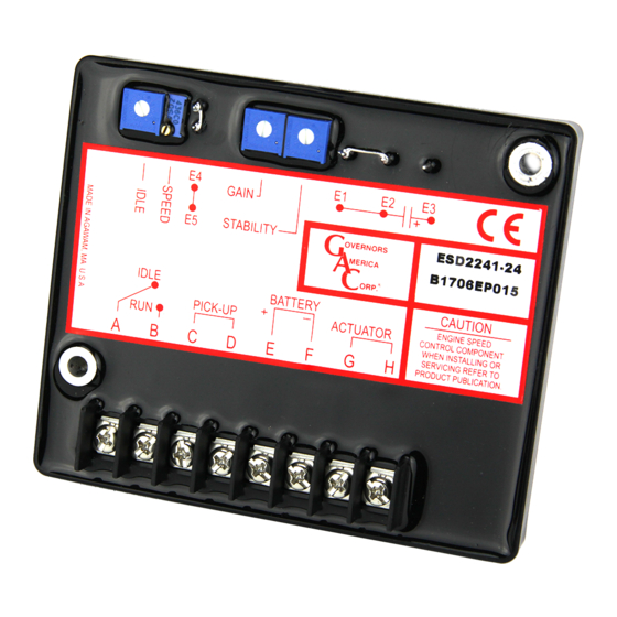
ESD2210
ESD2241
Standard Unit with Idle
For Hoist FT/Operates with Foot Pedal,
ESD2243
5000 Hz Speed Range
ESD2244
Light Force (Low-Current Optimized PID)
BATTERY
_
+
PICK-UP
ACTUATOR
C
D
E
F
G
H
15A
FUSE
S1
_
+
BATTERY
NOTES
#18 AWG (1.3mm sq) or larger wire
Wires must be twisted and/or shielded
for their entire length
Gap between speed sensor and gear
teeth should not be smaller than 0.02 in.
(.51mm)
Speed sensor voltage should be at least
1V AC RMS during crank
#16 AWG (1.3mm sw) or larger wire
A 15 amp fuse must be installed in the
positive battery lead to protect against
reverse voltage
Battery positive (+) input is Terminal E
#16 AWG (1.3mm sw) or larger wire
Standard Unit
4
STARTING THE ENGINE
IMPORTANT
The speed control unit governed speed setting is factory set at approximately
engine idle speed. (1000 Hz., Speed sensor signal or 600 RPM)
Crank the engine with DC power applied to the governor system. The actuator
will energize to the maximum fuel position until the engine starts. The governor
system should control the engine at a low idle speed. If the engine is unstable
after starting, refer to Section 5 ADJUSTING FOR STABILITY.
ACTUATOR
The governed speed set point is increased by clockwise rotation of
NOTE
the SPEED adjustment control. Remote speed adjustment can be
obtained with an optional 5K Speed Trim Control.
5
ADJUSTING FOR STABILITY
Once the engine is running at operating speed and at no load, the following
governor performance adjustments can be made to increase engine stability.
1.
Rotate the GAIN adjustment clockwise until instability develops. Gradu-
ally move the adjustment counterclockwise until stability returns. Move
Voltage
the adjustment one division further counterclockwise to insure stable
12V
24V
performance (270° pot).
X
X
2.
Rotate the STABILITY adjustment clockwise until instability develops.
Gradually move the adjustment counterclockwise until stability returns.
X
Move the adjustment one division further to insure stable performance
(270° pot).
X
3.
Gain and stability adjustments may require minor changes after engine
X
X
load is applied. Normally, adjustments made at no load achieve satis-
factory performance.
If instability cannot be corrected or further performance improve-
NOTE
ments are required, refer to Section 6
SHOOTING.
ESD2200 Electronic Speed Control Unit 10.14.16
2
Make sure the following adjustments are set before starting
the engine.
Gain
Middle Position
Stability
Middle Position
Speed Trim Control
Middle Position
(Infused)
25x
TORQE
E4
SPEED
GAIN
STABILITY
E5
E4
SPEED
GAIN
STABILITY
E5
START FUEL ADJUSTMENT
© 2016 Copyright All Rights Reserved
SYSTEM TROUBLE-
PIB 1022 D