Gage Bilt GB713 Manual de instalação - Página 4
Procurar online ou descarregar pdf Manual de instalação para Ferramentas Gage Bilt GB713. Gage Bilt GB713 14 páginas.
Também para Gage Bilt GB713: Manual de instruções original (18 páginas), Manual de instruções original (20 páginas)
PRINCIPLE OF OPERATION
When the air actuator assy is depressed, the pressurized air inside of the tool is released allowing spring pressure to move the
valve spool assy causing the air to be redirected. The air is directed to the top of the air piston assy, moving it in a downward di-
rection. The air below the air piston assy is then directed through the valve sleeve and exhausted out of the bottom of the tool.
Simultaneously, the piston rod assy connected to the air piston assy is also moving down, forcing hydraulic oil up and into the
front side of the head cylinder assy, causing the piston to move to the rear of the head cylinder assy. The internal components of
the attached nose assembly are also moving with the piston to start the fastener installation. When the fastener installation is
completed, the air actuator assy is released. Air pressure is then built up inside of the handle assy causing the valve spool assy to
return to its original position and reversing the sequence directing air pressure to the rear of the head cylinder assy, causing the
piston to move to the forward position.
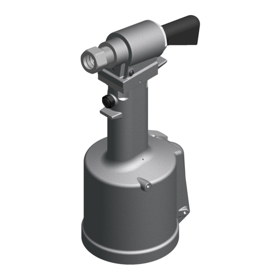
Image may not reflect actual tool
7/11 REV 10/14
4