Gage Bilt GB722 Manual de instalação - Página 6
Procurar online ou descarregar pdf Manual de instalação para Ferramenta eléctrica Gage Bilt GB722. Gage Bilt GB722 13 páginas. Installation tool
Também para Gage Bilt GB722: Manual de instruções original (20 páginas), Manual de instruções original (20 páginas)
DESCRIPTION
WARNING:
The balance of this tool is designed for horizontal use and is not ergonomically best
suited for all applications. Gage Bilt will be pleased to advise for your specific
application.
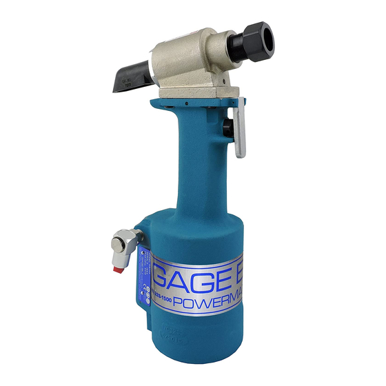
The GB722 is a pneumatic-hydraulic tool designed specifically for the efficient installation of a wide range
of blind rivets. It weighs 5.50 lbs. (2.49 kg) and can be operated in any position with one hand. It has
a .590" (15.0 mm) rivet setting stroke and a rated pull load of 4700 lbs (20.91 kN) with 90 psi (6.2 bar) air
pressure at the air inlet.
The GB722 riveter operates on a wide range of air pressure, with 90 to 100 psi (6.2-6.9 bar) providing the
maximum efficiency. At 90 psi. (6.2 bar) air pressure, the GB722 does not exceed 81.5 dB (A) and consumes
3 cfm at 20 cycles a minute.
The air inlet is provided with 1/4-18 female pipe threads to accept the users air hose fitting.
NOSE ASSEMBLIES ARE NOT FURNISHED WITH TOOL AND MUST BE ORDERED SEPARATELY.
MAINTENANCE
WARNING:
Maintenance personnel
WARNING:
Disconnect tool from its power source before performing maintenance.
WARNING:
Excessive contact with hydraulic oil and lubricants should be avoided.
WARNING:
Dispose of Hydraulic Oil in accordance with applicable regulations.
WARNING:
Read MSDS documents for all applicable materials.
The performance of any tool depends upon good maintenance practices. Following these minimal
requirements for service and care will extend the life of your tool.
*Only use an air supply set at 90-100 psi. (6.2-6.9 bar) equipped with a filter-regulator to prevent wear.
*The tool will eventually lose some hydraulic oil. Keep the hydraulic system full (only use Dexron III, or
equivalent) and free of air by using the air bleeder assy (704153) on a regular basis.
*Proper care by operator is necessary in maintaining full productivity and reducing downtime. Read all
applicable tool manuals and nose assembly data sheets prior to operating tools.
*Keep nose assemblies, especially jaws, clean and free of chips and debris.
*All Screwed End Caps, Base Covers, Air Fittings, Actuators, Screws and Nose Assemblies are to be
examined at the end of each working shift to check that they are secure.
*Check daily all Hoses, Couplings, and Tools for damage or air/hydraulic leaks. Tighten or replace (if necessary).
*For a complete overhaul, tool kit GB704TK is recommended.
CLEANING AND LUBRICATING PROCEDURE
Daily cleaning and lubrication of nose assembly
will greatly reduce downtime and increase life of
components. Using sewing machine oil, or an
equivalent cleaner/lubricant, follow instructions
below.
1. Disconnect tool vacuum line (if equipped).
2. Point nose assembly into oil as shown.
3. Cycle tool 8-10 times and wipe dry.
TORQUE SPECIFICATIONS
Button Head Cap Screws (A-928) = 40 inch lbs.
Packing Plug (704118) = 45 foot lbs.
Flexlock Nut (400559) = 40 inch lbs.
End Cap (722317) = 45 foot lbs.
Button Head Cap Screws (402482) = 35-40 inch lbs. (Do NOT over-tighten)
S/N: 1753 AND ABOVE
PLEASE CONTACT GAGE BILT FOR ALL OTHER SERIAL NUMBERS.
MUST
read and understand all warnings and cautions.
6
Image may not reflect
actual tool.
REV. 1/15