Hi-Force ATDP63 Manual de Instruções - Página 8
Procurar online ou descarregar pdf Manual de Instruções para Bomba de água Hi-Force ATDP63. Hi-Force ATDP63 15 páginas. Air driven hydrotest pumps
Também para Hi-Force ATDP63: Manual de instruções (9 páginas)
Operating Instruction Manual:
From Serial Number:
OM-ATDP-01
All
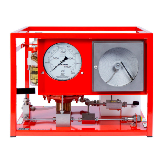
6.0 General Description
Hi Force ATDP Hydrotest pumps are designed to have an infinately variable output pressure and
displacement speed. They are fitted with an integral filtration and lubrication unit and air pressure
gauge. An airline regultor allows for easy setting of air inlet pressure and output hydraulic
pressure. The air start/stop valve allows for easy and fast pressure shut off. An air relief valve
(ARV) is fitted to the air inlet. The ARV is factory set to allow maximum pressure to be achieved
and vent any overpressurisation to the atmosphere.
The Hi-Force ADTP range of Hydrotest pumps are supplied in a range of 3 models with output
pressures ranging from 87 bar(1260psi) to 1489bar (21596psi) and are suitable for use with
various fluids. See 1.0 Specifications.
The ADTP air driven liquid pump range work on an automatic reciprocating differential area
piston principle that uses large area air drive pistons connected to smaller area hydraulic pistons
to convert compressed air power into hydraulic power.
The ADTP pump range has a double acting motion incorporating two hydraulic cylinder and
piston assemblies, as liquid is introduced into one hydraulic cylinder on the pump suction stroke,
liquid is automatically delivered from the second high pressure cylinder at the same time on the
pump delivery stroke and vice versa. When the pump reaches the end of its stroke the spool
valve in the air change over valve motor automatically shifts, reversing the pump direction; hence
delivery flow is relatively smooth with only a small interruption in flow (dwell) as the pump air
pistons change direction.
The units consist of a robust framework, fitted with an air driven hydraulic pump and complete
with all necessary hydraulic accessories i.e. a 150mm diameter hydraulic pressure gauge, a
hydraulic pressure release valve and all interconnecting pipe-work fittings and adaptors,
terminating at a single high pressure outlet connection port. Pneumatic accessories include an
air filter, air pressure regulating valve, oil lubricator, air gauge, ARV and air on/off valve.
A fluid inlet connection is provided and a Y type fluid strainer and fluid relief valve set at
approximately 10 bar is fitted between this connection and the pump inlet check valves.
Provision is provided for fluid drainage via a nylon hose connected to the hydraulic pressure
release valve.
The ATDP63 has a maximum working pressure of 434Bar (6,295psi) on the hydraulic pressure
circuit. The hydraulic pressure to be generated by the air driven pump is dependent upon the air
pressure applied i.e. Pump ratio 63/1: 1psig air drive pressure applied can generate 63psig
hydraulic pressure.
The ATDP125 has a maximum working pressure of 862Bar (12502psi) on the hydraulic pressure
circuit. The hydraulic pressure to be generated by the air driven pump is dependent upon the air
pressure applied i.e. Pump ratio 125/1: 1psig air drive pressure applied can generate 125psig
hydraulic pressure.
The ATDP216 has a maximum working pressure of 1489Bar (21596psi) on the hydraulic
pressure circuit. The hydraulic pressure to be generated by the air driven pump is dependent
8