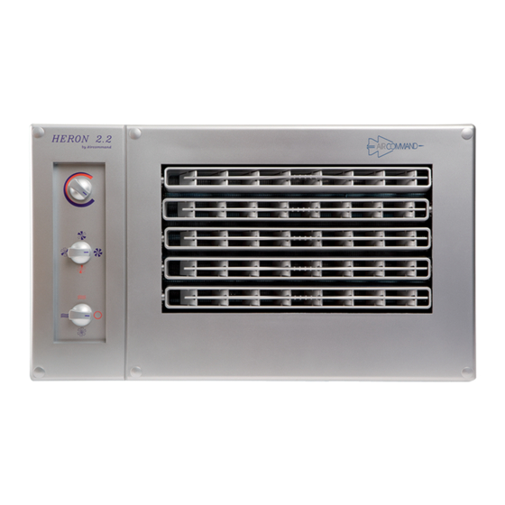
Aircommand HERON 2.2 Manual de instruções de instalação - Página 5
Procurar online ou descarregar pdf Manual de instruções de instalação para Ar condicionado Aircommand HERON 2.2. Aircommand HERON 2.2 10 páginas.
Também para Aircommand HERON 2.2: Manual do Proprietário (17 páginas)

I
Now Install the Air Handler (refer fig. 10, 11 & 12)
Insert the A/H into the front panel, and shift to the right as far as
possible such that the right hand flange is fully over the front panel.
Now insert a screw to hold the A/H in place while the copper tubes
are manipulated to line up with the respective nipples.
Mark any excess tube to be cut off, and remove the A/H to allow
the flare nuts to be put on and the flares made. Unscrew both flare
nuts from the nipples of the A/H, ensuring the sealing caps are
removed.
See page 5 for tips on making flares.
Having completed the flaring, reinstall the A/H, remembering to
shift it fully to the right after insertion. Screw the flanges back to
the front panel through the 4 holes provided. Couple the flare nut
connections and do up firmly.
POWER SUPPLY
The unit is designed to plug into a normal mains electricity supply.
This plug must be accessible after installation. If a new plug is installed,
then it must be positioned near to the airhandler and be easily accessible.
Note: The supply cord is designated Type F. If replacement is
necessary it should be replaced by an Aircommand
approved technician.
I Tips on Making Flare Joints
1. Always use a proper Tube Cutter to cut tube to length
(Never Ever a Hacksaw).
2. Remember to put the flare nut on the tube prior to making flare.
3. Always deburr the inside of the tube. Buy a proper deburring tool to
do this. It is a good idea to wipe around the inside of the tube to wipe
away any copper particles that may have come off during deburring.
NB. If an inside burr is left on, the flaring head will inevitably
drive this burr onto the surface of the flare, resulting in a
pitted flare face, which will almost certainly leak.
4. Clamp the tube in the flaring block firmly. For 1/4" tube (6.4Ø), the
unflared tube should protrude 1.0 mm. For 3/8" tube (9.5Ø) the
unflared tube should protrude 1.5 mm. See Fig. I, J & K
5. The flaring head should be lubricated with a smear of oil.
(Preferably vacuum pump oil).
Tighten down flaring head by:
a) Contact tube with flare head
b) Advance 3/4 turn
c) Back off 1/4 turn
d) Advance 3/4 turn etc, until flare has bottomed in the anvil (don't
tighten on the bottom).
This oscillating manner will ensure an accurate contour and guard
against splitting.
6. Check that the resulting flare shows a bright continuous ring around
the face, and no imperfections exist.
Back of Cupboard
90 Min.
Return Air Grille (3 off)
A. Correctly
B. Flare too small
C. Flare too large
D. Flare is uneven
E. Flare has burrs
5
AIR HANDLER
Drain Connection
Front of Cupboard
Figure 12
Flaring Head
Flaring Block
or Anvil
Chamber
Figure I
For 6.4Ø Tube,
1/3 H = 1 mm
For 9.5Ø Tube,
1/3 H = 1.5 mm
1
H
H
3
Figure J
FLARED FITTINGS
made flare
on edge
Figure K
Wing Nut
