Dynabrade 13460 Manual de Segurança, Operação e Manutenção - Página 2
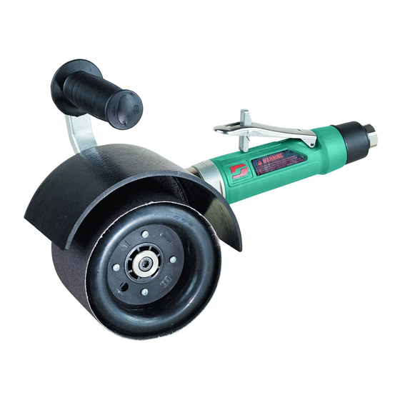
Procurar online ou descarregar pdf Manual de Segurança, Operação e Manutenção para Ferramentas Dynabrade 13460. Dynabrade 13460 8 páginas. 1hp right-angle. governor controlled 2,800 rpm and 2,800 rpm, versatility kit

Warning: Always wear eye protection. Operator of tool is responsible for following: accepted eye, face, respiratory, hearing and body protection.
Caution: Hand, wrist and arm injury may result from repetitive work, motion and overexposure to vibration.
• Keep hand and clothing away from working end of the air tool.
• Be sure that any loose clothing, hair and all jewelry is properly restrained.
• Secure inlet bushing on air tool with a wrench before attempting to install the air fitting to avoid damaging housing assembly.
• BEFORE MOUNTING A ACCESSORY, after all tool repairs and whenever a Dynisher
pressure set at 90 PSIG while the tool is running. If tool is operating at a higher speed than the RPM marked on the tool housing, or operating
improperly, the tool must be serviced and corrected before use.
Caution: Tool RPM must never exceed abrasive/accessory RPM rating. Check accessory manufacturer for details on maximum operating speed or special
mounting instructions.
• With power source disconnected from air tool, mount recommended accessory onto arbor assembly. Dynacushion should be mounted with valve stem accessible
for inflation. Inflate Dynacushion using 94465 Wheel Inflation tool. Inflate only enough to prevent abrasive from slipping or falling off.
DO NOT OVER-INFLATE DYNACUSHION (20 PSIG max.).
• Adjust handle support using 01678 Screw to desired position. The shroud assembly can also be adjusted using (3) 96278 Screw Assemblies to best protect
operator from abrasive debris during use. See Complete Assembly Breakdown for hardware locations.
• Connect air tool to power source. Be careful NOT to depress throttle lever in the process.
Do not expose air tool to inlet pressure above 90 PSIG or (6.2 Bars).
Caution: After installing the accessory, before testing or use and/or after reassembling tool, the right-angle Dynisher
for good balance. Gradually increase tool speed. DO NOT USE if tool vibration is excessive. Correct cause, and retest to insure safe operation.
• Make sure that work area is uncluttered, and visitors are at a safe range from the tools and debris.
• Air tools are not intended for use in explosive atmospheres and are not insulated
for contact with electric power sources.
• Use a vise or clamping device to hold work piece firmly in place.
• Do not apply excessive force on tool or apply "rough" treatment to it.
• Always work with a firm footing, posture and proper lighting.
• Ensure that sparks and debris resulting from work do not create a hazard.
• This tool is rear exhaust. Exhaust may contain lubricants, vane material,
bearing grease, and other materials flushed thru the tool.
Warning: Grinding/sanding certain materials can create explosive dust.
It is the employers responsibility to notify the user of acceptable dust levels.
• Grinding can cause sparks which can cause fires or explosions. It is
the users responsibility to make sure the work area is free of flammable materials.
• Contact with abrasive may cause abrasions or cuts.
Report to your supervisor any condition of the tool, accessories,
or operation you consider unsafe.
Regulator
Filter
90 PSIG
(6.2 Bar)
• Dynabrade Air Power Tools are designed to
operate at 90 PSIG (6.2 Bar/620 kPa) maximum
air pressure at the tool inlet, when the tool is
running. Use recommended regulator to control
air pressure.
• Ideally the air supply should be free from moisture.
Incorporating a refrigerated air dryer after the
compressor and drain valves at each tool station
(as shown) further reduces moisture from
condensation in the air supply.
OPERATING INSTRUCTIONS
Note: Diagrams are for mounting 3/4' I.D. Smooth Bore Wheels. For 1" I.D. Smooth Bore
Wheels use 96037 Adapters (sold separately) to reduce the wheel I.D. to 3/4" and follow
diagrams above for that width hub).
Air System
Lubricator
Closed Loop Pipe System
(Sloped in the direction of air flow)
To Tool Station
Filter
Ball
Valve
Drain
Valve
Drain
Valve
Air Tool
2
®
is issued for use, check tool RPM (speed) with tachometer with air
®
must be started at a reduced speed to check
Mounting Diagram
Typical
4"
Mounting of
wide accessories
1
2
3
1. 96264 Screw
3. 13375 Arbor
2. 13441 Long Flange
4. 50750 Spacer
Regulator
Lubricator
Air Hose
90 PSIG MAX
(6.2 Bar)
Drain Valve
Typical Mounting of 94473 and
94493 Pneumatic Wheels
1
5
4
3
5. 13434 Short Flange
LUBRICATOR SETTING
1 DROP/MIN.
20 SCFM
Air Flow
Refrigerated
Air Dryer
Ball
Valve
Air Flow
Air Compressor
and Receiver
