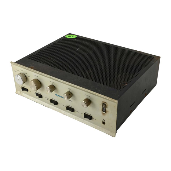
DYNACO SCA-80Q Manual de montagem - Página 12
Procurar online ou descarregar pdf Manual de montagem para Amplificador DYNACO SCA-80Q. DYNACO SCA-80Q 15 páginas. C9 replacement
Também para DYNACO SCA-80Q: Manual (12 páginas)

Connect the New Power Supply
All of the power connections are made in the same fashion:
1. Strip ¼" of insulation off each of the wires to be connected.
2. Insert the wire from the solder side of the board, and solder it on the component
side of the board.
Label
Number
with
of wires
3
4G
4
2G
2
1
1
Final Test and Assembly
Inspect your work:
1. Make sure that all the new wires are soldered in place.
2. Make sure that there are no solder bridges
Your SCA-80 should still be disconnected from your music system and it should still be
unplugged from the wall outlet.
Carefully plug in the SCA-80 to the wall outlet, taking special care to avoid contact with
the high voltage (either 120 V or 240 Volt) wiring inside the unit. Set your meter to DCV
and measure the following voltages with respect to the ground terminals on the power
supply board (or the chassis):
1. 24V should be between 22.75 and 25.25 Volts
2. 17.5 V should be between 17 and 18 Volts
3. 71 V should be between 65 and 77 Volts
Where wires connected
Any 3 of the 4 terminals on the PCB above the A
marking.
The 4 terminals about the double ground sign.
The two terminals above the single ground sign
Either of the two terminals above the E marking of the
PCB.
Either of the two terminals above the F marking of
PCB.
Page 12 of 15
Done()
