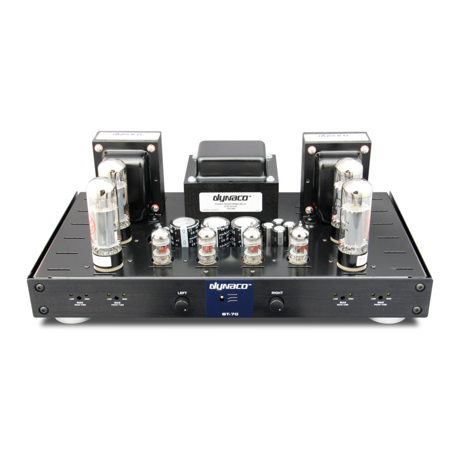
DYNACO ST-70 Manual de instalação e do utilizador - Página 3
Procurar online ou descarregar pdf Manual de instalação e do utilizador para Amplificador DYNACO ST-70. DYNACO ST-70 9 páginas. Driver 6gh8 ecf82 for the ab-q-st70 auto bias module
Também para DYNACO ST-70: Manual de montagem (14 páginas)

1. Remove the four 15.6 OHM bias resistors marked Rcatch V 2 to Rcath V 6 and disconnected to
wire cathodes V 2,3 to V 6,7
2. Install a new PC-3 driver board. The AB-Q module set also came with new spacers and screws.
Use them to reinstall the new PC-3 driver and connect all the original wires to the numbered
points on the driver.
3. Points 6 and 21 are disconnected from the bias potentiometers.
4. The wires can be connected to the AB-Q from above or below, depending on your taste. They are
usually connected from below.
5. Points 6, 6a, 21, 21a will be connected to the AB-Q module according to the diagram (GRD pads
V2, V3, V6, V7)
6. According to the picture we connect the cathodes V2, V3, V6, V7 EL34 to AB-Q (pads CATH V2,
V3, V6, V7).
7. It is necessary to maintain the exact order of the wires as shown. Change of positions the
connections will destroy the AB-Q module!
8. The wires in the two 6,3 AC pads should now be tightly twisted, as these are the 6.3VAC supply
wires for the AB-Q module and being AC, have to be twisted to ensure hum free operation!
