CEL-MAR ADA-4020-1-1-1-2-3 Manual do utilizador - Página 5
Procurar online ou descarregar pdf Manual do utilizador para Conversor de multimédia CEL-MAR ADA-4020-1-1-1-2-3. CEL-MAR ADA-4020-1-1-1-2-3 12 páginas. Rs-485 / rs-422 to current loop converter
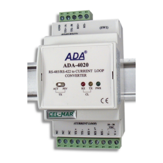
ADA-4020
The diagram of the transmitter & receiver is shown on figure below.
TX+
I= 0 / 20mA
or
I= -20 / +20mA
TX-
Active - Transmitter
2.5. ISOLATION
Converter ADA-4020 has 3-way, 1kV= or 3kV= galvanic isolation (depend on version). Converter versions are described in section
VERSIONS.
3. INSTALLATION
This chapter will show how to connect ADA-4020 to PC, RS485,RS422 buses and power supply and how to use it.
In the purpose of minimization of disruptions from environment is being recommended to:
● apply multipair shielded cables, which shield can be connected to the earthing on one end of the cable,
● arrange signal cables in the distance not shorter than 25 cm from powering cables.
● apply cable of adequate cross-section due to voltage drops for converter powering,
● use Interference suppression filters for power supply converters that are installed within a single object,
● not power the converter from power circuit device that generates large impulse interference such as transmitters, contactors,
3.1. ASSEMBLING
The ADA-4020 enclosure is adapted to assembly on TS-35 (DIN35) rail. To install repeater you should mount device on the rail upper
part of the enclosure then press bottom part to hear characteristic „Click" sound.
3.2. CONNECTION TO RS232 COMPUTER PORT
To connect the ADA-4020 converter to computer RS232 port should be used additional converter eg RS232 to RS485 ADA-I1040 or
USB to RS485 ADA-I9140. This converter should be connected with ADA-4020 via RS485 or RS422 bus as shown on the example
figure below.
TX+
I= 0 / 20mA
I
TX-
Passive - Transmitter
Fig 2. Review diagram of the transmitter & receiver Current Loop ADA-4020
3-WAY ISOLATION
RS485
Fig 3. Insulation structure
Current Loop
Power Supply
10 - 30VDC
5
U=12VDC / U=24VDC
R=560W / R=1000W
RX+*
RX+
RX-
Passive Receiver