HiB 33200 Manual do utilizador - Página 2
Procurar online ou descarregar pdf Manual do utilizador para Ventilador HiB 33200. HiB 33200 4 páginas. Hush & breeze wall mounted fans, timer, timer & humidity sensor
Também para HiB 33200: Instruções de montagem (3 páginas)
Technical Information -
Hush
Power input: 220-240 V, 50 Hz
Maximum ventilation volume: 97 m
Power consumption: 7.5W
Dimensions: W158 x H158 x D107mm
Breeze
Power input: 220-240 V, 50 Hz
Maximum ventilation volume: 88 m
Power consumption: 14W
Dimensions: W152 x H152 x D126mm
Fitting
1) Choose a suitable position for your fan
according to Figure 1 on the back page. Use
a cable finder to check if there are any buried
cables or pipes in the wall or ceiling. Draw
around the outside of the fan with a pencil to
determine it's exact position.
2) Make a suitable sized hole in the wall/
ceiling with the appriopiate tools.
N.B. If wall mounted ensure the hole is
angled slightly downward to stop any
moisture running back into the motor.
If mounted in the ceiling ensure the hole is
between the joists.
3) Fit flexible ducting into the hole, flush
with both sides of the wall. Ensure the
duct slopes slightly downwards towards
the outside. Make good any plasterwork
around the duct.
4) Position the fan back into place, and mark
the four fixing points. Drill the required
holes in the marked positions. If drilling
through tile, use a ceramic drill bit. Insert
wall plugs into the drilled holes.
5) Follow a similar procedure for the outside
wall grille.
6) If ceiling mounted the ducting should be
routed to the nearest soffit.
2
Electrical Connection
Hush
Please ensure that the fan unit is positioned in
accordance with the diagram below i.e. With
the electrical access point (5) top left.
/hr (±5%)
3
/hr (±5%)
3
1
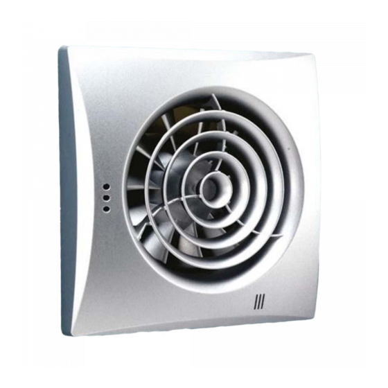
Casing
2
Fan propeller
3
Function module
4
Protective cover of terminal block
5
Electrical access point
Breeze
1
2
3
4
Fascia removal
Hush
fascia and gently prise away from the casing.
Breeze
maintenance, please remove the small retaining
screw and gently prise the fascia away from the
casing.
4
5
1
2
3
4
2
1
Holes for fan mounting (x4)
Terminal block
Electrical access points
Wire fixing rack
- Depress plastic nodule on the side of the
- In order to remove the fascia for
3