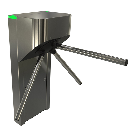
Automatic Systems TriLane TL1 Manual de início rápido - Página 7
Procurar online ou descarregar pdf Manual de início rápido para Torniquetes Automatic Systems TriLane TL1. Automatic Systems TriLane TL1 11 páginas. Tripod turnstile

p. 7/11
5.4. SITE PREPARATION WORK
This is basically the following:
• Study the set-up and positioning of the equipment according to the general layout of the site.
• Drill the holes in the floor according to the specifications of the Fig. 6, page 6.
• Be sure to drill the holes with a diameter suitable for the expandable dowels that you are going to use
type: model B15/30, ref.
• Check the correct location of the cable passage in the middle between the mounting holes (Fig. 6, page 6).
• Prepare the passage for the electrical control cables of the Central Control Station (not supplied) and the main
supply cables
If you add any device to the front or rear end boxes of the turnstile that could ignite
4.4.5), ensure that the installation surface is non-flammable.
5.5. INSTALLING THE TURNSTILE
• Position the turnstile precisely.
• Ensure that the turnstile remains firmly fixed to the ground by tightening the expandable dowels. Ensure that the
cables can pass through.
• Make sure that all the housings of the battery are perfectly aligned and horizontal. If needed, add shims between
the housings and the floor to ensure that they are perfectly level.
5.6. INSTALLING THE STAINLESS STEEL ARM (VERSION WITH FIXED ARMS)
• Put the arm (5.7) in place and push it into the housing until it stops.
• Align the threaded hole in the arm with the hole in the turret.
• Install the fan washer (5:1).
• Apply one drop of Loctite* 243
• With the dropping arm option, the 3 arms are installed from factory.
The information contained in this document is the property of Automatic Systems and is confidential. The recipient shall refrain from using this information for any purpose
other than the use of the products or the execution of the project to which it refers and from communicating it to third parties without prior written agreement of Automatic
Systems. The document is subject to change without notice.
-/3413/000).
(230V single-phase + earth, i.e. 3G x
5.4
Fig. 7 - Installing the stainless steel arm
(blue)
to the screw thread (5:8), and tighten.
TL1-QSG-EN-02
2.5). Provide 1.5 metres extra.
5.8
5.1
5.7
5.2
5.3
5.6
(recommended
(see EN60950 standard, paragraph
