GAI-Tronics SP2 Manual de instalação rápida - Página 2
Procurar online ou descarregar pdf Manual de instalação rápida para Amplificador GAI-Tronics SP2. GAI-Tronics SP2 4 páginas. Fiber handset/speaker amplifier station
SP2 Fiber Handset/Speaker Amplifier Station Quick Installation Guide
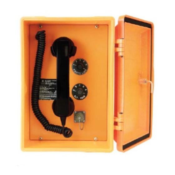
Figure 2. SP2 Station—Interior View
Available Settings and Adjustments
Most optional equipment is preconfigured to default settings at the
factory. The following is a partial list of the available adjustments and
settings that may be needed:
speaker volume
receiver volume
Installation
Mounting the Enclosure
Mount the enclosure using the four 0.312-inch (8 mm) diameter holes
located on the mounting flanges with ¼-inch (M6) hardware. The
suggested mounting height for all station enclosures is 48 inches (1219
mm) to the center of the bottom mounting holes of the enclosure. See
Figure 3 for mounting details. The SP2 Station is not supplied with
conduit or cable openings.
Remove the front panel and drill or punch entry openings in the rear
section of the enclosure. The station is suitable for bottom and/or top
entry. The recommended entry is via the enclosure bottom to prevent
moisture from dripping onto the termination board. Refer to Figure 3 for
the suggested locations of cable entry. There must be a minimum of ½
inch (13 mm) of material between entry holes.
Field Wiring
The SP2 Station provides terminal blocks on the termination PCBA
located in the rear enclosure for field wiring the power, speaker, and
RTU connections. Connect spade lugs to the wires before fastening
them to the termination board terminal blocks to obtain the most secure
connection. Torque the terminal block screws to 8–10 lb in (0.90–1.13
Nm) when attaching the spade lugs.
The main PCBA, mounted on the back of the front panel, contains the 600-ohm audio connection. Use ferrule terminals for
this connection. The fiber termination board is mounted on top of the main PCBA, which provides fiber optic termination to
the Ethernet SFP transceiver.
P:\Standard IOMs - Current Release\42004-xxxxQG Quick Guides\42004-795AQG.docx
08/17
series/parallel speaker connection
station ID and zone selector.
Pub. 42004-795AQG
Available Options
70/100V constant voltage termination board
with 24 watt output
24 V dc power supply
speaker/amplifier only (no handset)
headset with page pressbar
five configurable alternate page destinations
with selector switch
All-Call push button
PVC or Hytrel
®
handset cords in 6-, 15-, or
25-foot lengths
conformal PCBA coating
Figure 3. Suggested Wire Entry Locations
Page 2 of 3