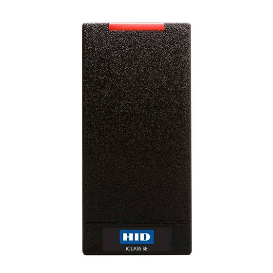
HID pivCLASS RPKCL40-P Manual de instalação - Página 2
Procurar online ou descarregar pdf Manual de instalação para Leitor de cartões HID pivCLASS RPKCL40-P. HID pivCLASS RPKCL40-P 8 páginas.

I N STALLATI ON GUI DE
Wiegand and OSDP Protocol
BASE PART
PRODUCT
NUMBER
R10-H
900N
RP10-H
900P
R40-H
920N
RP40-H
920P
RK40-H
921N
RPK40-H
921P
RKCL40-P
923N
RPKCL40-P
923P
Communication protocols other than Wiegand
1
or Clock & Data require an additional hardware
module which increases current by 30 mA.
Installation
1
Mounting
Attach Backplate and Mounting Gasket to Junction Box.
Contactless Models
This Installation Guide is for informational purposes only. HID makes no warranties, expressed or implied, in this summary. Company, product names and data used in sample output
are fictitious. Specifications are subject to change without notice.
© 2012 - 2018 HID Global Corporation/ASSA ABLOY AB. All rights reserved. HID GLOBAL, HID, the HID Brick logo, the Chain Design, and PIVCLASS are trademarks or registered
trademarks of HID Global, ASSA ABLOY AB, or its affiliate(s) in the U.S. and other countries and may not be used without permission. All other trademarks, service marks, and
product or service names are trademarks or registered trademarks of their respective owners.
h id g l o b a l.co m
CURRENT
INPUT VOLTAGE
Standby
Maximum
(VDC)
AVG
2
60mA
75mA
65mA
5-16VDC
12VDC for RS-485
85mA
85mA
95mA
12VDC
150mA
Standby AVG - RMS current draw without a card in the RF field.
2
Maximum AVG - RMS current draw during continuous PIV card reads.
3
Not evaluated by UL.
Peak - highest instantaneous current draw during RF communication.
4
Wiegand Cable Lengths: 100 ft (30.5 m) 22 AWG @ 5 - 6.4VDC
5
500 ft (152 m) 22 AWG @ 6.5 - 16VDC
Mounting holes for US single-
gang electrical boxes.
Install gasket for RK40 and
RPK40 models.
Junction box not included.
An ASSA ABLOY Group brand
pivCLASS
R10-H, RP10-H, R40-H, RP40-H, RK40-H, RPK40-H, RKCL40-P,
1
OPERATING
TEMPERATURE
PEAK
4
AVG
3
100mA
200mA
-30° to 150° F
110mA
(-35° to 65° C)
125mA
220mA
-4° to 122° F
185mA
250mA
(-20° to 50° C)
Reverse Configuration Rotating the backplate
180° allows for placing the Contact reader on left
and the Keypad reader on right.
See Section B Reconfigure Reader Assembly for
instructions, before proceeding to Section 2.
RPKCL40-P, RKCLB40-P
UL REF
CABLE LENGTH
5
NUMBER
R10Ex
Communication Lines
Wiegand = 500 ft - 22 AWG
RP10Ex
(152 m)
300 ft - 24 AWG
R40Ex
(91 m)
RP40Ex
RS-485 = Max. bus length
4000 ft - 24 AWG
RK40Ex
(1,219 m)
RPK40Ex
Max length between nodes:
RKCL40Ex
1,640 ft - 24 AWG (500m)
RPKCL40Ex
UL Reference Number Deciphering
x
Reader Colors:
K = Black
1
x
Wiring:
N = Pigtail
2
T = Terminal
x
Communications: N = No Module,
3
R = RS-485 (OSDP)
Contact Models
Mounting holes for US
double-gang electrical
boxes.
x
x
1
2
3
x
x
1
2
3
x
x
1
2
3
x
x
1
2
3
x
x
1
2
3
x
x
1
2
3
x
x
1
2
3
x
x
1
2
3
