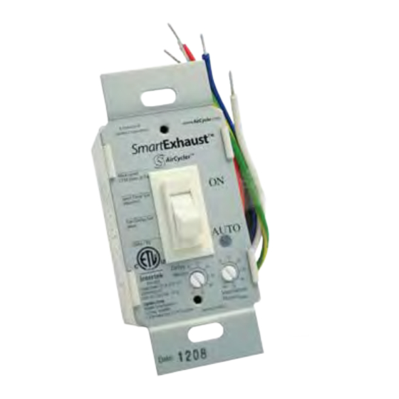
AirCycler SmartExhaust Manual de instalação e do utilizador - Página 2
Procurar online ou descarregar pdf Manual de instalação e do utilizador para Interruptor AirCycler SmartExhaust. AirCycler SmartExhaust 2 páginas.
Também para AirCycler SmartExhaust: Manual de instalação e do utilizador (5 páginas)

INTRODUCTION
The SmartExhaust
"'
is designed to replace bathroom fan
and light switches and provide both functions with one easy
operation. By using a microprocessor to monitor and control
"'
delivers a precise amount of
operation, the SmartExhaust
ventilation.
BE NEFITS
Works with ANY fan because it is NOT a solid state device
Earn LEED and ENERGY STAR points for enhanced
exhaust ventilation*
Make standard bath fans ASHRAE 62.2 compliant*
Replaces both fan and light switches for one easy
operation
Microprocessor technology provides precise ventilation
times
Programmable DELAY and VENTILATION settings
Excess manual and/or delay operation is subtracted
from the next hour's programmed ventilation time
Works with ALL Incandescent, CFL. fluorescent and LED
lights
*When used with ASHRAE 62.2 compliant fans
SAFETY CONSIDERATIONS
Read and follow manufacturer's instructions carefully. Follow
all local electrical codes during installation. All wiring must
conform to local and national electrical codes. Improper
wiring or installation may result in personal injury or product
and property damage.
WIRING DIAGRAM
B
et.UE
�
UGHf HOT
BtACK•
HDI
C.REEN,
C.RDI/NO
WlillE • NEllllW.
INSTALLATION INSTRUCTIONS
1.
TURN POWER OFF at circuit breaker or fuse panel.
2.
Remove cover plate and existing switch from wall box if
there is one already installed.
Connect the wires in the wall box using the supplied
3.
wire nuts. Wires must have ¾ inch of bare copper
exposed. Twist wires together tightly with supplied
wire nuts. Make sure no bare copper is exposed.
Secure connections with electrical tape. If a light i5 not
connected, be sure to attach a wire nut to unused blue
wire and secure with electrical tape.
4.
Mount SmartExhaust
"'
switch in to wall box with
supplied mounting screws.
5.
Set desired DELAY time by turning dial to desired
minutes.
6.
Set desired VENTILATION time by turning dial to desired
minutes per hour.
NOTE: To configure how much ventilation per hour
A
on
necessary, see Appendix
the rear
sheet.
7.
Record settings on face plate with an indelible marker
and snap rocker assembly onto face plate.
8.
Turn on power at circuit breaker or fuse box.
Note: To fully comply with ASHRAE 62.2 - attach clear ASHRAE
sticker to the face of the switch plate.
OPERATING INSTRUCTIONS
Move the toggle switch up to turn on the fan and light.
Move the toggle switch down to turn off the light The
fan will continue to run for the set DELAY time.
To cancel DELAY time for the toggle version, turn the
switch off and back on again within three seconds.
Within another three seconds, turn the switch off and
the fan will shut off canceling the DELAY for that use.
DELAY will not activate if the light/fan has not been on
for at least 10 seconds.
The fan will automatically come on once per hour for the
set VENTILATION time.
Any manual and/or DELAY fan operation will be
subtracted from the VENTILATION time for that hour.
If manual fan operation and DELAY operation exceed set
VENTILATION TIME, the excess time will be subtracted
from the next hour's set VENTILATION TIME.
OPERATION
The SmartExhaust
the two settings dials. If for example the VENTILATION dial
is set to 20 minutes/hour, the microprocessor will subtract
20 minutes from 60 minutes and determines that the
SmartExhaust
"'
and run for the remaining 20 minutes of that hour.
If the DELAY dial is set to 1 o minutes and the light/fan switch
is manually turned on for 5 minutes, the microprocessor will
keep track of the
off after the 5 minutes, the microprocessor will continue to
run the fan for the 10 minutes of DELAY setting adding up
to a total of 15 minutes. The 15 minutes will be subtracted
from the total required 20 minutes of VENTILATION time.
minutes into the hour, the fan will turn on and run for
55
the 5 additional minutes needed to complete the required
is
ventilation. See the diagram below for more details.
of
this instructi o n
A Normal Hour of Operation with no occupancy
The fan runs for
lO minu1es 10
satisfy the set
VENTILATION
time
45
The Bathroom Is occupied for 5 minutes
The fan runs for
minutes to satisfy the
remaining necessary
VENTILATION time
45
"'
has a microprocessor in it that reads
needs to come on 40 minutes into the hour
5
minutes of use. When the switch is turned
0-
15
30
S
more
0
The fan run, for
S minutes while
"'
the bathroom Is
occupied
The )an continues 10
run for 10 minutes
to satisfy 1he set
30
DELAYllme
P/N 780103200, 09/18 Rev A
