HID Vertx CS V100 Manual de instalação rápida - Página 5
Procurar online ou descarregar pdf Manual de instalação rápida para Controlador HID Vertx CS V100. HID Vertx CS V100 9 páginas.
- 1. QUICK START, VERTX (CS) V100 Door/Reader Interface Panel
- 2. Table of Contents
- 3. Introduction
- 4. Parts List (Included)
- 5. Product Specifications
- 6. Cable Specifications
- 7. Overview
- 8. Step 1 Preparations
- 9. What You Need before Getting Started
- 10. Step 2 Hardware Installation
- 11. Mounting Instructions
- 12. Wiring Vertx
- 13. Contact Information
VertX V100 (CS) Quick Installation Guide
Step 2
Hardware Installation
2.1 Mounting Instructions
1. The V100 should always be mounted in a secure area.
2. Mount the V100 using the four mounting screws (provided) or other appropriate fasteners. Place the
fasteners in the corner holes of the base.
3. The V100 panel can be stacked with or without the cover. Do not remove the plastic base. Make sure
to position the V100 panel in such a way as to provide room for wiring, air-flow and cable runs.
2.2 Wiring VertX
CAUTION: Connectors on the V100 sides are positioned to be mirror images and are not
interchangeable once the installation is complete. Therefore, you cannot unplug the connector from
one side of the board and plug it into the corresponding connector on the other side.
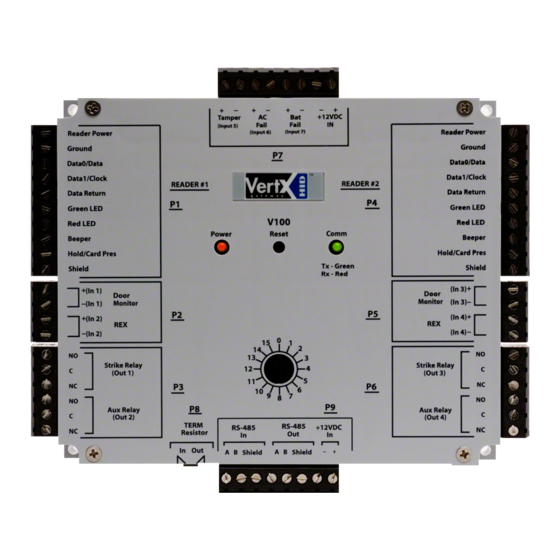
1. Power and Alarm input connections: Connect power by providing 12VDC to the P7 connector.
+12VDC goes to Pin 1 and Ground on Pin 2. The Bat Fail, AC Fail, and Tamper switch inputs are
wired as shown in the table. Connect the Bat Fail and AC Fail inputs to battery low/failure and AC
failure contacts provided on the power supply. Connect the Tamper input to a tamper switch on the
enclosure.
2. Reader Connections: Connect Wiegand or
clock-and-data interfaces to the V100 using
the connection table shown. You can
connect up to 10 signal lines for the reader.
Use as many of the signal lines as required
for your reader interface.
Note: Connect the data return line to the
same ground as the reader power if the
reader is not powered by the VertX units
12VDC.
August 2005
Pin #
1
2
3
4
5
6
7
8
9
10
2005 © HID Corporation. All rights reserved.
Pin #
P7
1
+12VDC
2
Ground
3
Bat Fail -
4
Bat Fail +
5
AC Fail -
6
AC Fail +
7
Tamper -
8
Tamper +
V100 P1
V100 P4
Reader Power
Shield Ground
Ground
Hold
Data 0 / Data
Beeper
Data 1 / Clock
Red LED
Data Return
Green LED
Green LED
Data Return
Red LED
Data 1 / Clock
Beeper
Data 0 / Data
Hold
Ground
Shield Ground
Reader Power
Page 5 of 9