Gain Electronic SAGA1-K Series Manual de instalação e operação - Página 14
Procurar online ou descarregar pdf Manual de instalação e operação para Controlo remoto Gain Electronic SAGA1-K Series. Gain Electronic SAGA1-K Series 17 páginas. Industrial radio remote control
Chapter 2. System Configuration
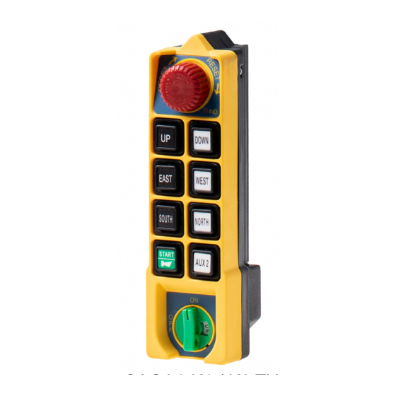
2–1 Transmitter Unit
Pushbuttons
The transmitter unit consists of an Encoder Circuit and a Transmitter RF Circuit.
When the user presses a pushbutton on the transmitter, the Encoder Circuit senses
the pushbutton's data immediately. The Encoder Circuit then encodes the
pushbutton's data, combined with the ID Code and a Hamming Code to become
the "control data".
This control data goes to the transmitter RF circuit to modulate a radio frequency
(RF) carrier. The output FM signal from the modulator is then sent to the antenna
to generate the transmission signal via an RF amplifier and a low-pass filter.
2–2 Receiver Unit
Control data
ANT
The receiver unit consists of the Receiver/Decoder module and the Relay module.
RF signals (control data) from the transmitter are received by the antennas and sent
Encoder
Circuit
Figure A. Transmitter block diagram
Command
Receiver/
Decoder
Module
Figure B. Receiver block diagram
Data
Transmitter
RF Circuit
Cable
Relay
Module
13
Control Data
Antenna
Relay contact outputs
(Connects to cranes
or other mechanical
devices)