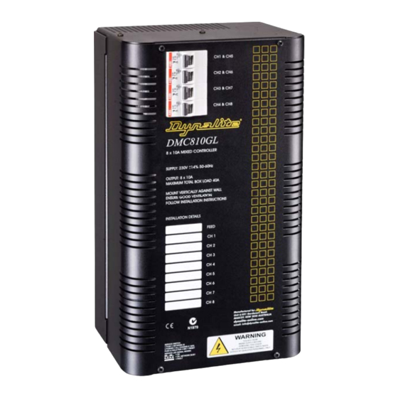
Dynalite DMC810GL Manual de instalação - Página 6
Procurar online ou descarregar pdf Manual de instalação para Controlador Dynalite DMC810GL. Dynalite DMC810GL 12 páginas. Leading edge dimmer/hf ballast controller

Connecting Serial Control Cables
Connecting Data Cable
Connect Data Cable in a 'Daisy Chain'
RJ12 Socket Connections
Serial Cable Permanent Connections
.........................................................................................................................
Determine Your Requirements
Serial ports are used to interconnect other
dimmers, smart control panels, sensors and AV
controllers. Serial port devices can be identified by
6 terminals, labelled: SHLD, GND, DATA+, DATA-,
+12V, AUX.
Serial Cable Connections
There is one RS485 port for DyNet signals, in the
form of a RJ12 socket, on the front panel, which is
used for the temporary connection of a PC or a
DTK601 Portable Programmer. Data terminals on
the control card shall be used for permanent
connections. Cable for connections to the serial
port shall be screened, stranded RS485 data cable,
with three twisted pairs. Recommended cable types
include:
Belden:
9503
Dynalite:
DYNET-STP-CABLE
Garland:
MCP3S
Hartland:
HCK603
M&M Cable:
B2003CS
M&M Cable:
B9503CS
Multicables:
AWM E120236 2092 20
RS Components:
368-687
One pair is paralleled for GND, one pair paralleled
for +12V and one pair used for DATA+ and DATA -.
Recommended Cable Colour Coding
Green/White pair: Paralleled for GND
Orange/White pair: Paralleled for +12V
Blue/White pair: Blue for DATA+
Brown/White pair: Spare or for Join
The colour-coding scheme used is not critical, as
long as the same scheme is used throughout the
installation.
Serial Cable Connecting Method
The recommended connecting method is to 'daisy
chain' devices (starting at the first device, then
looping in then out of devices, with a single cable
terminating at the last device. There should not be
any spurs or stubs, and only the first and last
device shall terminate one cable. All other devices
should terminate two cables).
wired in any order.
segregated from any mains cables. A data cable
that is connected to an energised dimmer is live.
Do not cut or terminate live data cables. If the data
cable has to cross over any mains cables, it is
recommended that it do so at a 90
minimise noise coupling. Sufficient insulation shall
be
provided,
subject
DMC810GL Instruction Manual Rev B.DOC
White for DATA-
Devices may be
The data cable should be
angle to
to
local
regulations.
6
