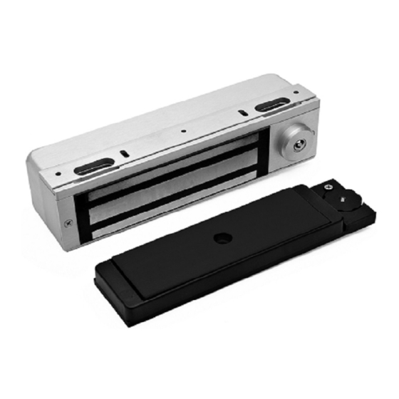
DynaLock 3101B-TJ101 Instruções de cablagem - Página 2
Procurar online ou descarregar pdf Instruções de cablagem para Fechaduras DynaLock 3101B-TJ101. DynaLock 3101B-TJ101 13 páginas. Electromagnetic lock
Também para DynaLock 3101B-TJ101: Instruções de montagem (4 páginas)

705 Emmett Street Bristol, CT 06010
1-877-DynaLock www.dynalock.com
Remove the Electronics Cover to expose the circuit board assembly.
1.
V
J4
J3
1 2 3 4 5 6 7 8 9 10 11 12 13 14 15 16 17 18 19 20 21 22 23 24
V
- Voltage Selection
2.
Check that the voltage
selection jumper (J4) is
properly set to match your
input power. Note that all
locks are factory set for 24
volts.
FA
- Fire Alarm Control
3.
Check that the fire alarm
co ntrol j umper ( J 9) is
properly set to match your
fire panel input contacts.
If fire panel tie-in is not
required leave jumper at
factory setting (N.O.).
C
4.
- System Selector Switches
The selector switches (DS1) that control major system
functions are factory set to the OFF position for basic lock
operation. Switch 1 will be used during sensor adjustment
(page 8). Switches 2, 3 and 4 are only used for options
described on page 5.
3101B-TJ101 MANUAL
BASIC SET-UP
REMOVEABLE JUMPERS
(Factory Setting)
NO
C
NC
SET FOR
NORMALLY OPEN
INPUT
Page 2
MODEL 3101B-TJ101
DELAY EGRESS SYSTEM
WIRING INSTRUCTIONS
C
1 2 3 4
DS1
LED 1
CONNECTOR
FA
J9
(Factory Setting)
SET FOR 24 VOLTS
NO
C
NC
SET FOR
NORMALLY CLOSED
INPUT
(Factory Setting)
ON
1 2 3 4
DS1
STANDARD SOFTWARE
VERSION 2K1.1
SET FOR 12 VOLTS
03/11
