dB Technologies DVA T12 Manual do utilizador - Página 3
Procurar online ou descarregar pdf Manual do utilizador para Sistema de altifalantes dB Technologies DVA T12. dB Technologies DVA T12 18 páginas.

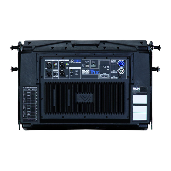
CONTROLS AND FUNCTIONS
"Balanced Audio" section
1)
" INPUT" INPUT CONNECTOR
Balanced input at line level. It is able to accept "XLR" sockets.
2)
"LINK" OUTPUT CONNECTOR
The "XLR" connector connected in parallel with input (1) can be used to send the input
audio signal to another amplified speaker.
"Status" section
3)
"LIMITER" INDICATOR LIGHT
This indicator comes on red to indicate that the internal limiter circuit has tripped.
This prevents amplifier distortion and protects the speakers against overloads.
Always avoid operating conditions where the system works for long periods of
! !
time with LED flashes or it is always ON
4)
"SIGNAL" INDICATOR LIGHT
This indicator comes on green to indicate the presence of an input signal to a level
higher than-20dBu.
5)
"MUTE/PROT" INDICATOR LIGHT
This yellow indicator indicates amplifier status. In normal operating conditions, the LED
is off; if it flashes or is always on, refer to the diagnostics table to check amplifier status.
6)
"READY" INDICATOR LIGHT
This indicator comes on green to indicate that the main power voltage is correct. In
normal operating conditions, the LED is on; if it flashes or is off, refer to the diagnostics
table to check amplifier status.
"Input control " section
7)
"INPUT SENS" INPUT SENSITIVITY CONTROL
This control regulates the sensitivity of the signal amplifier input.
This control does not affect the "BALANCED LINK/OUT" output level
"RDNET " section
8)
INPUT CONNECTOR "DATA INPUT"
RJ45 connector 'data input.
9)
OUTPUT CONNECTOR "DATA INPUT"
RJ45 connector 'data output for cascading connections.
10)
"LINK" INDICATION LIGHT
This green indicator turns on only when the amplifier has recognized and is
connected with the main RDNET unit via the computer.
11)
"ACTIVE" INDICATOR LIGHT
This yellow indicator flashes when there is an active data transmission between
RDNET and the amplifier module.
10
