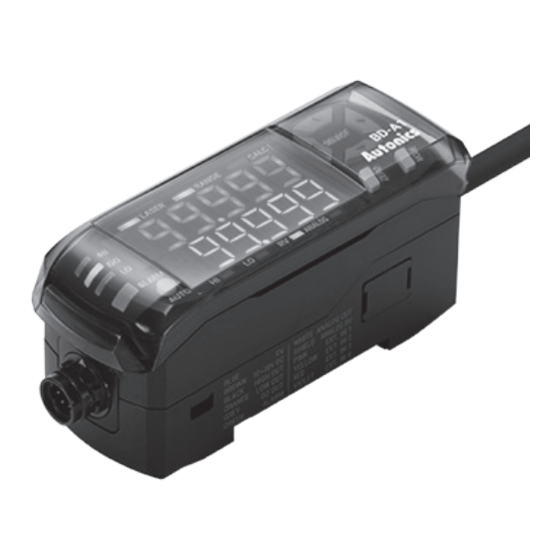
Autonics BD-100 Manual do produto - Página 4
Procurar online ou descarregar pdf Manual do produto para Acessórios Autonics BD-100. Autonics BD-100 6 páginas. Laser displacement sensors
Também para Autonics BD-100: Manual (14 páginas), Manual do produto (5 páginas)

[Sensor head] Installation Precautions
For stable measurement, mount the sensor head by referring to the below items.
■ Moving object measurement
Object with material / color difference
Install the emitter and receiver in parallel
to the material or color boundary of the
object.
Object with step
Install the emitter and receiver vertically to the
line between crest and valley of the object.
■ Narrow area or concave object ■ Wall mounting
Install the sensor head where the reflected
laser beam does not blocked toward the
receiver part.
■ Black object
When measuring black object with low
reflectance the amount of light received
decreases, install the sensor head closely
to the object.
Installation
■ Sensor head
• Mount to the panel directly or through the bracket
M3 bolt
by using M3 bolt and nut (tightening torque: ≤ 0.5
N·m).
• Check the mounting position considering emission
M3 nut
Emission
center line, vibration and shock.
center line
■ Amplifier unit
- Mounting with bolt
• Mounting without DIN rail is possible by using bracket.
• The method of mounting and detaching with bracket is as same as DIN rail.
- DIN rail installation
1. Insert the bottom
holder of amplifier
unit to 35 mm width
DIN rail.
2. Push the front part
of the unit to arrow
direction to mount.
■ Ferrite core (accessory)
Sensor head
Within 30 mm from the sensor head, wind
the cable through the inside of the ferrite
core three times and mount the ferrite core.
Rotating object
Install the receiver and the rotating shaft
in parallel to minimize the influence of
fluctuations and position deviations.
Install the sensor head where the reflected
laser beam from the wall does not enter
the receiver part. If the color of wall is black
with low reflectivity and no gloss, the error
can be minimized.
- Removing from DIN rail
1. Side amplifier unit
ⓑ
ⓐ
to ⓐ direction.
2. Pull the assembly
part to ⓑ direction
to detach.
Extension cable (sold separately)
Within 30 mm from the connector of
amplifier unit, wind the cable through the
inside of the ferrite core three times and
mount the ferrite core.
■ Connecting to amplifier
unit
1. Connecting: Insert connector of the
sensor head into amplifier unit with
aligning ↑ mark and ▲ mark until it
sounds click.
2. Disconnecting: Pull out the connector
cap of sensor head to the opposite
direction.
■ Distinguishing master/slave amplifier units
When the power cable direction is down, the amplifier at the left end is the master unit,
and the channel number of slaves increases sequentially to the right.
Master
■ Precautions when connecting amplifier unit
• Mount on DIN rail.
• Do not supply the power when adding amplifier unit.
• Supply power to each connected amplifier unit at the same time.
• Up to 8 amplifier units can be connected, and only 1 calculation function can be
performed per 1 group of mutually connected amplifiers.
• When the calculation function is activated, the SV of the slave units are disable and the
mutual interference prevention function for sensor heads is executed automatically.
[Amplifier unit] Display When Power is ON
Displays control output setting screen when connecting a sensor head and supplying
power at the first time, or replacing a sensor head. Set the output type as below
sequence.
Refer to 'Mode setting' to check the setting range and the reset method.
1. Control output type
PV display
OUT
When 'OUT' is displayed
on the PV display, select
Description
control output type
through the [▲], [▼] keys
and push the [MODE] key.
[Amplifier unit] Mode Setting
Sensing
[AUTO] key over 2
→
sec
optimization
Zero-point
[ZERO] key over 2
→
sec
adjustment
HIGH sensitivity
[MODE]+[▲] key
→
over 2 sec
adjustment
LOW sensitivity
[MODE]+[▼] key
→
adjustment
over 2 sec
RUN
Auto sensitivity
[MODE] key within
→
(Teaching)
2 sec
Control output
[MODE]+[AUTO]
→
key over 2 sec
→ HIGH PEAK value
[▲] key
→
LOW PEAK value
[▼] key
[MODE] key over 2
→ Parameter group
sec
■ Connecting amplifier units
mutually
②
①
③
1. Remove the side cover at the connecting side.
2. Connect the side connector to the units.
3. After mounting amplifier unit on DIN rail, push it
to arrow direction tightly.
• In case of disconnecting, follow the upper
sequence reversely.
• Max. 8 units
Slave
2. Analog output type
3. Entering RUN mode
A-OUT
OUtSET
When 'A-OUT' is displayed
After 'OUT.SET' is
on the PV display, select
flashed three times and
analog output type
it returns to the run
through the [▲], [▼] keys
mode.
and push the [MODE] key.
Auto
Start: [ZERO] key within 1
sec
Stop: [ZERO]+[MODE] key
over 2 sec
Set digit: [◀], [▶] key
Set value: [▼], [▲] key
Save: [MODE] key within 2
sec
Auto
Set value: [▼], [▲] key
Save: [MODE] key
Auto after flashing OUT.SET
type
in PV display and END in SV
display part 3 times
[◀], [▶], [▼], [▲] key or
auto after no key input for
5 sec
[MODE] key over 3 sec
→
→
→
RUN
→
→
→
→
