Autonics SFC-A322-2 Manual - Página 4
Procurar online ou descarregar pdf Manual para Controlador Autonics SFC-A322-2. Autonics SFC-A322-2 13 páginas. Safety controllers / safety relay unit
Também para Autonics SFC-A322-2: Manual (13 páginas)
Connections
■ Basic unit: SFC-422-□
Power
Safety Input 1
Safety Input 2
Feedback
Start Input
Auxiliary
Output
Safety
Output
■ Non-contact door switch
unit: SFC-N322-23□-□
Expansion
Power
Output
Safety Input 1
Non-Contact
Door Switch
Input
Safety Input 2
Feedback
Start Input
Auxiliary
Output
Logic Input
Safety
Output
■ Relay unit:
SFC-R□12-□
Power
Safety Input 1
Safety Input 2
Feedback
Start Input
Auxiliary
Output
Safety Relay
Output
Only For
SFC-R412-□ Model
■ Advanced unit:
SFC-A322-23□-□
Expansion
Power
Output
Safety Input 1
Safety Input 2
Feedback
Start Input
Auxiliary
Output
Logic Input
Safety
Output
■ Expansion relay unit:
SFC-ER412-□
Expansion
Expansion Input
Output
Power
Auxiliary
Output
Safety
Relay Output
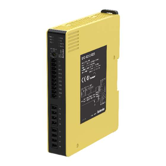
■ Relay unit:
SFC-R212-R2□-□
Power
Safety Input 1
Safety Input 2
Feedback
Start Input
Auxiliary Output
Safety Relay Output
Off-Delay
Instantaneous
Wiring of Input
■ A1, A2: Power supply input
The input terminals for power supply. Connect the positive side (24 VDCᜡ) of the
external power supply to the A1 terminal and connect the negative side (GND) of the
external power supply to the A2 terminal.
■ M11, M12: Safety input 1, M21, M22: Safety input 2
To turn ON the safety outputs, ON state signals must be input to both safety input 1 and
safety input 2.
• 1-channel safety input
• 2-channel safety input
24 VDCᜡ
24 VDCᜡ
■ M51, M52, M53: Feedback start input
• Auto start
To turn ON the safety outputs, the feedback loop must
remain ON state.
• Manual start
To turn ON the safety outputs, the feedback loop must
remain ON state and the signal input to M52 must be
changed from OFF state to ON state, and then to OFF
state.
(The duration that the start switch is in the ON state: min.
100 ms)
■ M61, M62: Logic input
Connect the safety outputs of the upper unit to the logic (AND) input of the lower unit.
To use the logic input function, SW1 and SW2 of switch for setting function must be set
to ON state.
Up to four units (advanced / non-contact door switch unit) can be connected as logic
(AND) connections in parallel per safety output.
Up to four units can be connected in serial logic (AND) connection.
Up to 20 units can be connected to the entire unit via logic connection.
Basic unit can only be used in layer 1.
Layer 1
Layer 2
Layer 3
Series connection:
max. 4 units
• Logical AND Connections
Unit
No. of units connected to logical AND connections Max. 4 units
Total no. of units connected to logical AND
connections
No. of layers for logical AND connections
Cable length for logical AND connections
• Response time and Operating time
Max. response time
Configuration
Item
(ON → OFF)
Layer
Expansion unit
Excepts
Basic / Advanced / Non-
Layer 1
15 ms
contact door switch unit
Layer 2
30 ms
Layer 3
45 ms
Advanced / Non-contact
door switch unit
Layer 4
60 ms
Layer 5
75 ms
■ D1, D2, D3, D4: Non-contact door switch input
All the non-contact door switch inputs connected to the non-contact door switch SFN
Series must be ON as a required condition for the safety outputs to be ON. Up to 30 non-
contact door switches can be connected.
For more information, refer to the non-contact door switch SFN Series instruction
manual.
Wiring a single switch
Wiring multiple switch (up to 30 units)
24 VDCᜡ
Feedback
loop
24 VDCᜡ
Feedback
loop
24 VDCᜡ
Start
switch
Parallel connection:
max. 4 units
Basic / Advanced /
Non-contact door switch unit
Max. 20 units
Max. 5 layers
Max. 100 m
Max. operating time
(OFF → ON)
Includes
Excepts
Includes
25 ms
50 ms
80 ms
40 ms
250 ms
280 ms
55 ms
450 ms
480 ms
70 ms
650 ms
680 ms
85 ms
850 ms
880 ms
...
...
...
...