DYNANAV DynaFlight3 Manual - Página 10
Procurar online ou descarregar pdf Manual para Ecrã de aviónica DYNANAV DynaFlight3. DYNANAV DynaFlight3 18 páginas. Aerial application guidance and management system

IO ControlBox
Overview
The IO ControlBox has multiple functions to interface the aircraft and the pilot to the DynaFlight system.
These functions are as follows:
◼
To interface to sense the spray on/off of the aircraft system.
◼
To protect the DynaFlight from the electrical spikes generated by any relay action
◼
To protect the DynaFlight system from static discharge on the control switches.
To interface multiple styles of control switch assemblies or to the DynaGrip™ control grip.
◼
Placement
The IO ControlBox does not need to be hard mounted, however for vibration isolation, it would be best to
secure it to the aircraft surface.
Wiring
The IO ControlBox has Red and Black wires that are respectively required to connect to power and ground.
The Green wire is for Marking the GPS Spray on/off. This requires power supplied to it to be Spray On. For
Pressure switches on the Spray Boom, make sure the pressure is well within the range of the normal boom
pressure for spraying. If you have a DynaNav DynaFlow.
The IO ControlBox is connected directly to the DynaFlight 3 interface harness, by connecting the 3 pin
male and female CanBus connectors coming from each of the DynaFlight 3 and the IO ControlBox.
Wiring Harness Diagrams
Overview
The diagrams attached to appendix are for the interconnect wiring of the DynaNav system. All wires on the
harnesses supplied (except the control grip/box)
Supplied Parts List
Basic DynaFlight 3™ airborne system contains:
Part Number .............................................................................. Description
1)
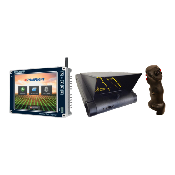
DynaFlight HMI ................ DynaFlight 3 Processor/GPS Touchscreen
2)
DynaViz III ......................... DynaViz III™ Electro-luminescent display unit
3)
DB-3-Display Cable ......... DynaViz III Cable 3-foot Display cable
4)
5BO16A-XT-1 ................... GPS, GLONASS, L Band Antenna
5)
DB-AntCable14-E ............ Antenna Cable 14' TNC to SMA
6)
DB-3-Power Cable ........... Power with Laser and Com (for flow control, etc.) connectors
7)
DynaGrip™/ Switch kit ... Military spec 5-way Top Hat control switch as well as other switches with 8
foot cable assembly. (for Helicopters, switches provided)
8)
DB-3-ControlBox ............. Relay box for sensing of spray on/off and control switch input
9)
DB-3-Control Cable ......... Spray on/off 9 ft. wire and CanBus interface connector
10)
DB-3-Aux Cable ............... DynaFlight 3 Cable for USB, CanBus and Relay out (AutoSpray) .
11)
Dual Lock ......................... 1 feet peel and stick locking fastener
730 – 11731 BAYNES ROAD, PITT MEADOWS, BC, CANADA, V3Y 2B4
WEB PAGE:
www.dynanav.com
EMAIL: [email protected]
9
PHONE: 604-465-0009
FAX: 604-465-0084
