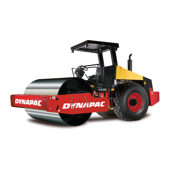
Dynapac CA260 Manual de oficina - Página 18
Procurar online ou descarregar pdf Manual de oficina para Equipamento de construção Dynapac CA260. Dynapac CA260 20 páginas. Vibratory roller

- 1. Table of Contents
- 2. Introduction
- 2. Warning Symbols
- 2. Safety Information
- 2. General
- 3. Safety Regulations
- 3. Before Start
- 3. Start
- 3. Jump Starting
- 3. Electrical and Hydraulic Equipment
- 4. Type of Electrical Circuit Diagram
- 4. DYNAPAC Electric Wiring Standard
- 4. Wiring System
- 5. Electrical Circuit Diagrams
1
2
=Head light switch
2.1
B.1
F2.2B1
F2.2
1
241 RD
2
2
S16.X1
F2.12
2.2
20A
B.2
F2.2B2
4.00 mm²
2.2
1
246
5
RD
5
S16.X1
964 BK
7
7
0.75 mm²
S16.X1
9
9
S16.X1
963 BK
0.75 mm²
242 RD
962
244
BK
RD
4.00 mm²
8.1
8.1
H.1
F1.78
F1.8
F1.78
H.1
8.2
10A
H.2
F1.78
H.2
X.26:1
/10.B1
#1631.1
245 RD
=Flash relay
K9
K9.X1
660 YE
49A
49a
49
49
31
K9.X1
K9.X1
31
#494.2
730 BU
0.75 mm²
6
X6
/2.B4
X.6
6
W i r e a r e a 1 . 5 m m u n l e s s o t h e r w i s e s t a t e d
L e d n i n g s a r e a 1 . 5 m m d ä r a n n a t e j a n g e s
3
S16
l
0
ll
S16.X1
120 WH
2.50 mm²
1
X.11
3
3
X11
1
1
121
WH
S16.X1
6
6
S16.X1
4
4
623 YE
S16.X1
8
8
624
S16.X1
YE
10
10
620 YE
2
X.11
X11
2
630 YE
1
X12
X.12
1
965
966
BK
BK
0.75 mm²
0.75 mm²
669 YE
S21
X.515
l
0
ll
661 YE
S21.X1
2
3
3 S21.X1
2
S21.X1
1
1
662
664
663
YE
6
YE
0.75 mm²
YE
5
S21.X1
0.75 mm²
4
7
S21.X1
7
8
8
S21.X1
9
S21.X1
967
9
10
BK
10
0.75 mm²
=Hazard switch
670
671
S17
YE
YE
l
650 YE
0
3
2
1
18
S17.X1
18
17
S17.X1
17
5
5
S17.X1
10
10
S17.X1
961 BK
=Break light relay
K10
86
85
730 BU
1
K10.X1
K10.X2
85
30
87
30
K10.X1
K10.X1
87
87a
4
Rev.
120 WH
2.50 mm²
56A
E10.X1
122 WH
=Position direction right/ front
3
X.11
669 YE
X11
3
1
1
E15/H18.X1
620 YE
1
2
E15/H18.X2
630 YE
621
YE
669 YE
663
YE
1
622 YE
661 YE
665
YE
663 YE
2
X12
X.12
2
X.516
1
670 YE
X.12
X12
670 YE
3
3
X.513
4
X12
632 YE
X.12
4
650
YE
631 YE
150 WH
652 YE
651 YE
980 BK
960 BK
Designed
Approved
Material Designation
TKZ/GE
TKZ/LW
View
Date
Description
20070125
E
Reg.
5
Pls.
Issued by
Change No.
Date
=Headlight right
E10
56A
X
31
E10.X1
968 BK
2.50 mm²
56B
X
31
31A.X18
969 BK
=Headlight left
E9
56A
56A
X
31
E9.X1
E9.X1
56B
31
X
E15/H18
3
E15/H18.X3
970 BK
1
31A.X19
972 BK
=Position direction left/ front
E13/H15
1
1
3
E13/H15.X3
971 BK
E13/H15.X1
1
31A.X20
1
2
E13/H15.X2
=Direction side right
H20
H20.X2
1
1
2
=Direction side left
H20.X1
1
H17
1
1
2
H17.X2
973 BK
H17.X1
1
E14/H26/H16
E14.X1.1
1
1
661 YE
H26.X1.1
2
4
E14.X2.1
1
1
978
BK
31A.X23
H16.X1.1
3
1
E16/H27/H19
1
X.514
E16.X1.1
1
1
976
BK
H27.X1.1
2
4
E16.X2.1
1
1
H19.X1.1
3
1
Part No
Model
CA250 T1
Circuit diagram
Scale
Driving light
Kretsschema
Rev.
Trafikbelysning
6
Checked
Headlight
1
A
Right/ front
Headlight
Left/ front
Position/
direction
1
Right/ front
Position/
direction
1
Left/ front
B
Direction/
side
Right
Direction/
side
Left
Position
Left/ rear
Break light
Left/ rear
Direction
1
Left/ rear
977
BK
C
Position
Right/ rear
Break light
Right rear
1
Direction
31B.X9
Right/ rear
1
31B.X10
D
Sheet / of
6
/
14
No.
393809
