Galaxy 3500Msi Manual de instalação e do utilizador - Página 6
Procurar online ou descarregar pdf Manual de instalação e do utilizador para Produto de canalização Galaxy 3500Msi. Galaxy 3500Msi 17 páginas.

WARNING:
DO NOT FIT A TAP ON THE
SHOWER OUTLET.
WARNING:
TAKE CARE TO AVOID
RESTRICTING THE OUTLET OF THE
PRESSURE RELIEF DEVICE.
c) ELECTRICAL
WARNING:
THIS SHOWER MUST BE EARTHED.
The electrical installation must be in accordance
with the current BS.7671 (IET Wiring
Regulations) and 'Part P' of the Building
Regulations and/or local regulations
1. The shower unit is designed for a single phase
AC electrical supply.
Please check the rating plate on the unit to
see what details apply to your shower.
AS A GUIDE ONLY (* only applies if external earth
Cable
Rating
Sizes
4.0mm²
6.0mm²
7.2 / 6.6kW
240 / 230V
6.0mm²
10.0mm²
6.0mm²
8.5 / 7.8kW
10.0mm²
and
9.5 / 8.7kW
6.0mm²
240 / 230V
10.0mm²
impedance is less than 0.35 Ohms)
Remember to upgrade the cable if it runs in
thermal insulation in a loft, or for longer distances.
2. A means for disconnection in all poles must
be incorporated in the fixed wiring in
accordance with the wiring rules.
We recommend a ceiling switch mounted in
a convenient position.
3. Cut back cable (fig.6).
Connect cable to
terminal block making
sure that all the
retaining screws are
VERY TIGHT
and that no cable
insulation is trapped
under the screws.
4. Regularly tighten terminal blocks - BS 7671.
Cable
Fuse / MCB
Length
32A
21m Max.
Type B MCB
35m Max.
40A
27m Max.
Type B MCB
45m Max.
40A
27m Max.
Type B MCB
45m Max.
45A
12m Max.*
BS.1361 fuse
21m Max.*
6
WARNING:
FAILURE TO COMPLY WITH THESE
INSTRUCTIONS COULD RESULT IN
FAILURE OF THE TERMINAL BLOCK
WARNING:
THE UNUSED SUPPLY TERMINAL
BLOCK MUST NOT BE USED FOR
ANY OTHER PURPOSE.
5. Refit the detachable lower section onto the
backplate with the 2 x fixing screws (fig.2).
Ensure
6.
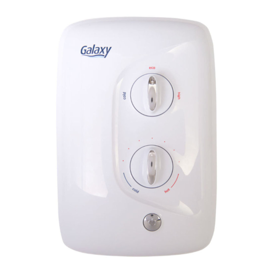
power select Knob is aligned to the
'cold' graphic (9 o'clock), whilst the 'D-Shaft'
in the product is aligned as shown (fig.7).
7
Ensure
temperature Knob is aligned to 'cold'
graphic, whilst the 'spindle' in the product is
fully
rotated
anti-clockwise as shown (fig.8)
8
WARNING! KNOB ALIGNMENT IS VERY
IMPORTANT – SEE DETAIL ON PAGE 15
Refit the front cover, and secure by replacing
the top and bottom fastening screws.
Ensure
that power select knob has been
correctly aligned by ensuring that all 3 power
settings can be selected.
Ensure
that temperature knob has been
correctly aligned by turning from minimum to
maximum flow (approximately 1 full turn).
6. Assemble Shower Accessories (fig.9 White
Models), or see Sheet provided (Chrome).
6
