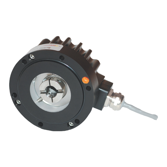
DYNAPAR NorthStar HSD44T1024A3A-01 Manual de instalação - Página 5
Procurar online ou descarregar pdf Manual de instalação para Conversor de multimédia DYNAPAR NorthStar HSD44T1024A3A-01. DYNAPAR NorthStar HSD44T1024A3A-01 6 páginas. Extreme heavy duty encoder

MECHANICAL INSTALLATION
STEP 1: Please reference the below diagram
titled "EN 44 Motor Mount Requirements" to
ensure that a correct mounting interface is
provided for the mechanical installation of this
encoder. The HSD44 has a 0.110 inch piloted
face that is concentric with the Flex Coupling.
Be sure to create a concentric pilot with the six
1/4-20 inch threaded holes on customer equip-
ment as shown in the diagram.
STEP 2: Ensure the mounting interface and shaft
extension are free of dirt, grease, or any other
foreign matter. Check the shaft Total Indicated
Run-out (TIR), and ensure that it does not exceed
0.005" TIR.
STEP 3: Using the 1/4" hex key, remove the Shaft
Clamp Access Plug from the side of the encoder
body.
STEP 4: Place the 9/64" ball end hex key into the
access hole and loosen the Shaft Collar Clamp
Screw. Place a small amount of threadlocker on
the screw threads and re-install it into the Clamp
Collar. Re-thread the screw into the clamp
loosely. DO NOT TIGHTEN. Remove the 9/64"
ball end hex key from the access hole.
STEP 5: Place a Lockwasher onto each
1/4-20 x 1" Encoder Mounting Screw (6 required).
Apply a small amount of threadlocker to the screw
threads.
STEP 6: While observing the proper orientation of
the cable exit, slide the encoder straight over the
motor shaft extension, and engage the encoder's
Flex Coupling. Note again, shaft engagement is
MIN 0.47" MAX 0.83".
Note: Please refer to 'HSD44 Coupling/Clamp
Installation" figure (previous page) when perform-
ing Installation Steps 7 – 11.
STEP 7: Install the six Encoder Mounting Screws
using the 3/16" hex key and torque to 75 inch
pounds.
STEP 8: Using the 9/64" hex key, tighten the Shaft
Clamp Screw. Torque to 45 inch pounds. Remove
the 9/64" hex key.
CAUTION: The motor shaft must NOT be
rotated until Step 9 (below) is performed,
or damage to the encoder flex coupling will
result.
STEP 9 Using the 5/32 hex key, completely remove
the 10-32 x 1.5" Flex Coupling Location Screw.
This screw is no longer needed for installation,
instead replace with the shorter 10-32 x 7/8" screw.
Obtain the 10-32 x 7/8" SHCS from the hardware
kit (this screw has an o-ring under the head). Ap-
ply a small amount of threadlocker to the screw
threads. Using the 5/32" hex key install the screw
into the Coupling Locating Hole and torque to 20
inch pounds. The purpose of this shorter screw is
to block the hole while in operation.
STEP 10 Apply a small amount of threadlocker to
1/8" NPT Shaft Clamp Access Plug threads. Using
the 1/4 hex key, install the plug and torque to 60
inch pounds.
Page 5
