Galaxy Audio DHXR4 Manual de início rápido
Procurar online ou descarregar pdf Manual de início rápido para Sistema de microfone Galaxy Audio DHXR4. Galaxy Audio DHXR4 2 páginas. Any spot wireless microphone system
Também para Galaxy Audio DHXR4: Manual do utilizador (20 páginas)
GAL A X Y AUDIO
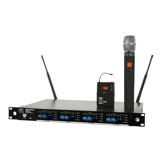
Included Components
1.
1.
DHXR4 x1
2.
Antennas x2
3.
Rack Ears x2
4.
1/4" to 1/4" Audio Cable x1
2.
5.
Power Supply x1
6.
BNC Connectors x2
7.
5.
BNC Cables x2
8.
Screws x6
9.
Antenna Plugs x2
10.
Quick Start Guide x1
Setup
1
Insert the 5.5mm plug into the DC input
jack, plug the wall wart into a 120VAC
outlet.
Rack Mounting
(Optional)
1
Attach the rack ears using the provided
screws.
2
Press the "SET" button twice, the group
number will flash, use the up and down
buttons to select a group.
3.
4.
6.
7.
8.
9.
2
Individual Outputs: Connect a shielded
microphone cable to each channel's
XLRM output needed, connect the other
end into your mixer input.
Front Mount Antenna
(Optional)
1
Attach the BNC feed-through connectors
to the rack ears.
3
Press set again, the channel number will
flash, use the up down buttons to select
a channel.
Optional Accessories
10.
1.
HH65SC Handheld Mic
GAL A X Y AUDIO
Q uick Start Guide
Included Components
Optional Accessories
What May be Needed
1.
1.
10.
1.
1.
to Rack
DHXR4 x1
HH65SC Handheld Mic
(Not Included)
2.
Antennas x2
2.
HH65 Handheld Mic
2.
2.
3.
Rack Ears x2
3.
MBP77 Body Pack
1.
Rack Screws 10/32 x .75",
HH65 Handheld Mic
4.
1/4" to 1/4" Audio Cable x1
3.
4.
4.
LV-U3BK Lav Mic
5.
Power Supply x1
2.
5.
AS-GTR Guitar Cable
3.
4.
Phillips Truss Head Screws
6.
BNC Connectors x2
6.
HS-U3BK Headset Mic
7.
2.
#2 Phillips Head
7.
5.
6.
7.
8.
7.
5.
Screwdriver
BNC Cables x2
SM-W77 Shockmount Base
8.
Screws x6
6.
9.
Antenna Plugs x2
9.
1.
2.
10.
Quick Start Guide x1
Setup
3.
1
2
3
4
5
MBP77 Body Pack
Insert the 5.5mm plug into the DC input
Individual Outputs: Connect a shielded
Combined Outputs: 1/4" Connect one
Combined Outputs XLR Connect one
Attach the antennas to the antenna jacks
jack, plug the wall wart into a 120VAC
microphone cable to each channel's
end of a shielded 1/4"M to 1/4"M cable
end of a shielded microphone cable to
outlet.
XLRM output, connect the other end into
to the 1/4" Mix output, connect the other
the mix XLRM output, connect the other
4.
LV-U3BK Lav Mic
your mixer input.
end into your system input.
end into your system input.
Rack Mounting
Front Mount Antenna
Operation
(Optional)
(Optional)
1
1
2
3
1
1
5.
AS-GTR Guitar Cable
Attach the rack ears using the provided
Attach the BNC feed-through connectors
Attach the short BNC cables to the rear
Power on the receiver
screws.
to the rack ears.
panel antenna jacks, and to the BNC
feed-through connectors on the back of
the rack ears.
2
3
4
4a
5
Follow steps 2, 3 and 4 of "Operation"
for each channel. Use the same group,
6.
but a different channel for each.
HS-U3BK Headset Mic
Ex: Group 1; Channels 1, 2, 3 and 4.
Press the "SET" button twice, the group
Press set again, the channel number will
With the transmitter turned on, place the
4b
number will flash, use the up and down
flash, use the up down buttons to select
transmitter with it's IR window (figure 4a)
buttons to select a group.
a channel.
facing the receiver IR window (figure 4b),
about 6" away. Press the ADS button on
channel 1.
7.
SM-W77 Shockmount Base
3
Combined Outputs: 1/4" Connect one
end of a shielded 1/4"M to 1/4"M cable
to the 1/4" Mix output, connect the other
end into your system input.
2
Attach the short BNC cables to the rear
panel antenna jacks, and to the BNC
feed-through connectors on the back of
the rack ears.
4
With the transmitter turned on, place the
transmitter with it's IR window (figure 4a)
facing the receiver IR window (figure 4b),
about 6" away. Press the ADS button on
channel 1. This will sync the Transmitter
to the Receiver.
1.
2.
3.
4.
7.
5.
6.
4
Combined Outputs XLR Connect one
end of a shielded microphone cable to
the mix XLRM output, connect the other
end into your system input.
3
Attach the Antenna to the front end of
the BNC Connectors.
4a
4b
Quick Start Guide
What May be Needed
to Rack
(Not Included)
1.
Rack Screws 10/32 x .75",
Phillips Truss Head Screws
2.
#2 Phillips Head
Screwdriver
1.
2.
5
Attach the antennas to the antenna jacks
Operation
1
1
Power on the receiver
Follow steps 2, 3 and 4 of "Operation"
5
for each channel. Use the same group,
but a different channel for each.
Ex: Group 1; Channels 1, 2, 3 and 4.