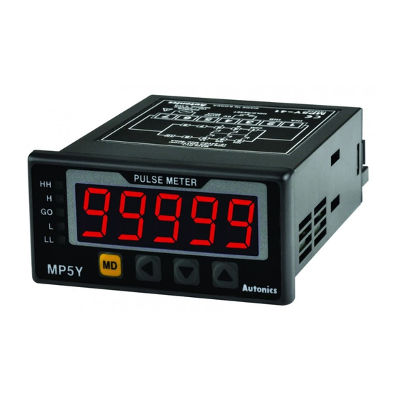
Autonics MP5W Series Manual de instruções - Página 6
Procurar online ou descarregar pdf Manual de instruções para Instrumentos de medição Autonics MP5W Series. Autonics MP5W Series 8 páginas. Multi pulse meters

■ F5: time interval
Displays measured time of input A ON.
Time interval (T)
= t
Display value Display unit
SEC
MIN
999.99 s
999.99 m
(default)
9999.9 s
9999.9 m
Time interval
99 m 59.9 s
99 h 59.9 m
9 h 59 m 59 s
999 h 59 m
99999 s
99999 m
Input A
t1
ta
t2
Hold
Display
t1
• ta: Return time (≥ 20 ms)
■ F6: time differential
Displays measured time from Input A ON to Input B ON.
Time differential (T)
= t (ta to tb)
Display value Display unit
SEC
MIN
999.99 s
999.99 m
(default)
Time
9999.9 s
9999.9 m
differential
99 m 59.9 s
99 h 59.9 m
9 h 59 m 59 s
999 h 59 m
99999 s
99999 m
Input A
Input B
ta
Hold
t1
t2
t3
t4
Display
t1
t2
t3
• ta: Return time (≥ 20 ms)
■ F7: absolute ratio
Measures and displays relative speed, amount, speed, etc. of input B against input A
in percentage (%).
Input B
Absolute
=
× 100 %
ratio
Input A
Frequency of input B [Hz] × Bα
Absolute
=
ratio
Frequency of input A [Hz] × Aα
Display value Display unit
Absolute ratio %
Frequency of input B [Hz] × Bα
Display =
× 100 [%]
Frequency of input A [Hz] × Aα
Input A
fA
Input B
fB
■ F8: error ratio
Measures and displays the relative rate of input B against the reference value of
input A in percentage (%).
Input B - Input A
Error
=
× 100 [%]
ratio
Input A
(frequency of input B [Hz] × Bα)-
Error
=
(frequency of input A [Hz] × Aα)
ratio
Frequency of input A [Hz] × Aα
Display value Display unit
Error ratio
%
Input A
fA
Input B
fB
• t: measured time of input A ON [sec]
Motor
Stamp
ta
t3
t2
t3
• t (ta to tb): measured time from input A ON
to input B ON [sec]
Sensor B
Sensor A
t5
t6
t7
t4
t6
t7
• Aα: prescale value of input A
• Bα: prescale value of input B
× 100 %
Flow meter A
Liquid
MP5
• Hold
When the hold signal turns ON, the display
value is maintained until the display cycle
turns to hold OFF.
• Aα: prescale value of input A
• Bα: prescale value of input B
Conveyor A
× 100 [%]
MP5
• Hold
When the hold signal turns ON, the display
value is maintained until the display cycle
turns to hold OFF.
■ F9: density
Measures and displays the density ratio (%) of input B against the total sum of input
A and input B.
Density =
Input A + Input B
Frequency of input B [Hz] × Bα
Density =
(frequency of input A [Hz] × Aα)
+ (frequency of input B [Hz] × Bα)
MP5
Display value Display unit
Density
Input A
fA
Input B
fB
■ F10: error
Measures and displays the error of input B against reference value of input A.
Error
= Input B - Input A
= (frequency of input B [Hz] × Bα) -
Error
(frequency of input A [Hz] × Aα)
Display value Display unit
Error
MP5
Input A
fA
Input B
fB
■ F11: length measurement 1
Measure and display the number of input A pulses during input B ON.
Length measurement 1 = P × α
Display value Display unit
Length
measurement
1
Flow meter B
Input A
1
2
Input B
Hold
Display
• ta, tb: Return time (≥ 20 ms)
■ F12: interval
Measures and displays the number of input A pulses from input B ON to the next
ON.
Interval
= P × α
Display value Display unit
Conveyor B
Interval
Input A
1
Input B
Hold
Display
• ta: Return time (≥ 20 ms)
Input B
× 100 [%]
× 100 [%]
%
• Hold
When the hold signal turns ON, the display
value is maintained until the display cycle
turns to hold OFF.
END User setting unit
• Hold
When the hold signal turns ON, the display
value is maintained until the display cycle
turns to hold OFF.
• P: number of input A pulses
• α: prescale value
Quantity [EA]
Input A
(default)
mm
cm
m
3
4
5
6
1
2
1
2
3
4
tb
ta
6 × α
2 × α
• P: number of input A pulses
• α: prescale value
Quantity [EA]
(default)
mm
cm
m
2
3
4
5
1
2
3
4
1
ta
5 × α
4 × α
• Aα: prescale value of input A
• Bα: prescale value of input B
Flow meter A
Flow meter B
Liquid
MP5
• Aα: prescale value of input A
• Bα: prescale value of input B
Conveyor A
Conveyor B
MP5
Input B
Photoelectric sensor
MP5
4 × α
MP5
Photoelectric sensor
2
3
