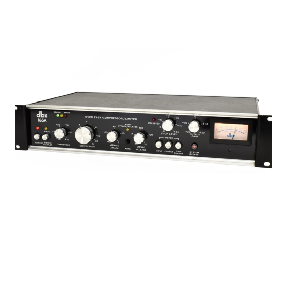
dbx 165A Manual de instruções - Página 5
Procurar online ou descarregar pdf Manual de instruções para Compressor de ar dbx 165A. dbx 165A 17 páginas.

4
F
ig.
2
-
Rear Panel
Signal
Output
These term inals feed
the program processed by the
16
5 to
the
nex
t device i
n
t he audio path.•
Signal Inp
ut These term
i
nals
accep
t
the inco
mi
ng aud io program for
processing by t he Mode
l
165. •
-
SIGNAL
-,
,
INPUT
+
! -
+
OfTEC TOA
INPUT
OUEC10A
INPUT
SIGNAL
l
oorPu1I
+
! -
Detector Input
The 165 comes from the factory
with these term
i
nals stra
p
ped to t he adjacent
Signal Input(+)
and(
-
) terminals. If you wish to
gain
access to the 165's Detector Inp
u
t for
insertion of an aux
ii
iary device, yo
u
may do so
by remov
i
ng the strappi
ng,
wiring the auxiliary
device's output to the 165's Detector Input
termina ls, and feeding t he auxi
l
iary device's input
w
i
t
h
the
sam
e signal fed to t he 165's
Signal
Input.
In certa
i
n situations, the signal processor (auxiliary
dev ice) may need to be i nserted in the
signal
pat
h
,
not in the detector path
.
(This wou ld be the case
w hen a delay
l
ine is used to achieve a "preview"
of
the
signal
.) I
n
such cases, signal is fed to the input
of the auxi
l
iary device, and also to t he detector input,
and the
aux
i
l
iary dev ice's out
p
ut is fed to the 165
signal
i
np ut.
Un less t he i nstallation is permanent, the con
-
nections described above
can
be awkward. There-
fore we recommend wiring a few Tip/Ring Sleeve
phone jacks
10
the
16
5
i
nstead, " normal
lin
g" the
jacks so that t he Signal Inp
u
t-to-Detector
Input link
is no rmally estab
li
shed via the jacks, b
u
t is
automatica lly disconnected whenever a plug is
i nserted
i
n t he Detector
I
nput jack
.
A simi lar
j
ack
may be used for the
16
5 output. (See Figure 6 for
in
f
ormatio
n
on w iring of these jacks.)
Ste reo
Coupler
When a suitab le cable
j
oins this con-
nector to the Stereo Coup ler co nnector o
n
anot her
Mode
l
165, and when one of the un
i
ts is switched to
"slave" mode, the two
u ni
ts may then be ut
i
lized for
process
in
g a stereo program. A m ulti-pin male con-
nector is supplied with
each
165 so the coupler cab le
can be
assem
bled using the w
i
ri ng diagram i
n
F igure 7.
NOT
E: On ly two Mode
l
165's can be coup led
together
.
Four units cannot be coup led togethe
r
for
quad
(4
-channel) operation
.
Fo
r
this purpose we
recommend t he use of two dbx Model 162 stereo
compressor /
I
im
i
ters.
Fuse For Mode ls sold in the U.S.A ., th is 1 /
4
amp,
250 vo
l
t
A
GC type fuse
p
rotects the primary side
of the unit's 117V AC power supply. Be
su
re to
replace a b lown f use with one of t he same size and
type. If the fuse blows cons istentl
y,
co ntact the db
x
factory or yo ur dbx dealer.
Sfl:AE:O
COU
PL[A
Meter Calibr at ion Con
tro
l
This recessed,
screwdriver-adjustable
trimmer may be
used to precisely calibrate t he ,neter
so O VU
I
nput o
r
Output leve
l
is
equiva lent to
any
where fro
m
-
10 dB
(245 mV) to + 10 dB (2.45 V).
MODEL 1&5
0
AC Powe
r
Cable
Connect t his
cable to a
11
7 VAC, 50 or
60 Hz AC power source
onl
y
. Models for use wi
t
h
other power sources outside
the United States are
avai
lable. Contact the db
x
facto ry for
in
formation.
T
he Mode
l
165 requires a
max
im
um
of 1 5 watts AC
power.
*A udio High (+), chassis ground('#-), and
A
udio
L
o
w
(-) terminals
are provided for connection
of the 765
I
nput and Output to
balanced or floating lines
(i.e.,
two
conductor shielded audio cables).
For use with an unbalanced line (i.e., a single conductor shielded
cable}, it is necessary to connect a jumper between the (-} and
(~) input terminals. No jumpers are necessary for the output
terminals when input jumpers are used. The Detector
I
nput has
only audio high (+) and low(-)
terminals, and it shares the
chassis terminal with the Signal Input.
