Autonics LE365S-41 Manual - Página 3
Procurar online ou descarregar pdf Manual para Temporizador Autonics LE365S-41. Autonics LE365S-41 12 páginas. W48×h48mm, weekly/yearly timer
Também para Autonics LE365S-41: Montagem (11 páginas)

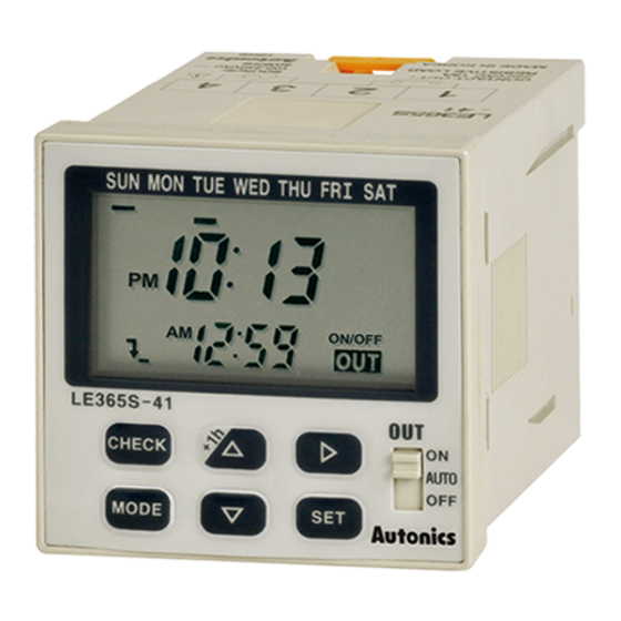
Unit Description
1
2
3
4
5
6
7
8
9
1. Day indicator
2. Day display
● Light: Day is selected.
● Light-out: Day is not selected.
3. Current time setting mode indicator
4. DST display (daylight saving time)
5. AM/PM display (main display)
6. Season display
7. Program display
8. Display ON time/day, OFF time/day, ON time width,
OFF time width
9. AM/PM display (sub-display)
10. YEAR display
: It turns ON when set, check, modify, delete yearly
program, set yearly holidays and operate yearly
program.
11. Yearly START/STOP day display
12. Main display
Functions
Definitions
● Record: A part of program that controls output operation.
● Step: Basic component of Record.
Operation modes
● If the operation mode of Program 1 (program 2) is set on
pulse mode initially, the pulse mode is fixed for additional
programs. If the operation mode of Program 1 (program
2) is set on ON/OFF or cycle mode initially, pulse mode
cannot be used for additional pulse programs.
● If the weekly operation mode is set on ON/OFF or cycle
mode, the yearly operation mode is fixed on ON/OFF
mode.
If the yearly operation mode is set on ON/OFF, the
weekly operation mode is fixed on ON/OFF or cycle
mode.
● If the weekly operation mode is set on pulse mode, the
yearly operation mode is fixed on pulse mode. If the
yearly operation mode is set on pulse mode, the weekly
operation mode is fixed on pulse.
19
20
21
Weekly/Yearly Timer
10
11
12
13
14
15
16
17
18
22
23
13. Remaining step display
14. Operation mode display
15. Output mode display
16. Year, month, date display
17. Unit of pulse width display
18. Sub display
19. CHECK key
20. MODE key
21. Operation key
: Press
key over 3sec in RUN mode, DST mode is
+1h
set and released.
22. SET key
23. Output selection switch
● AUTO: Control output according to the set program.
● ON: Output is ON. (operation)
● OFF: Output is OFF. (block)
●Weekly ON/OFF mode
Output operation by ON/OFF set time.
• Min. time setting unit: 1 min
• It is able to set ON/OFF day separately.
• One record in two steps
(ON day/ON time, OFF day/OFF time)
ON Time
●Weekly Cycle operation
It outputs ON the set ON time width which is from Cycle
operation ON time to Cycle operation OFF time, and it
outputs OFF the set OFF time width.
(A)
Photoelectric
Sensors
(B)
Fiber
Optic
Sensors
(C)
Door/Area
Sensors
(D)
Proximity
Sensors
(E)
Pressure
Sensors
(F)
Rotary
Encoders
(G)
Connectors/
Connector Cables/
Sensor Distribution
Boxes/Sockets
(H)
Temperature
Controllers
(I)
SSRs / Power
Controllers
(J)
Counters
(K)
Timers
(L)
Panel
Meters
(M)
Tacho /
Speed / Pulse
Meters
(N)
Display
Units
(O)
Sensor
Controllers
(P)
Switching
Mode Power
Supplies
(Q)
Stepper Motors
& Drivers
& Controllers
(R)
Graphic/
Logic
Panels
(S)
Field
Network
OFF Time
Devices
(T)
Software
K-91
