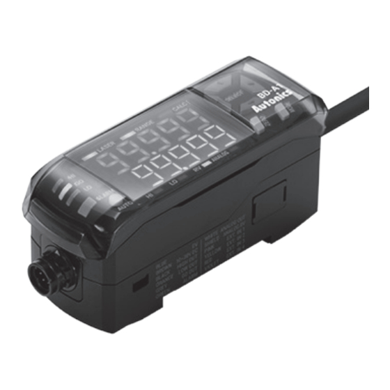
Autonics BD Series Manual - Página 12
Procurar online ou descarregar pdf Manual para Sensores de segurança Autonics BD Series. Autonics BD Series 14 páginas. Laser displacement sensors amplifier unit
Também para Autonics BD Series: Manual do produto (6 páginas), Manual do produto (5 páginas), Manual do produto (3 páginas)

-|Transparent setting
▣ Display When Power is ON
Displays control output setting screen when connecting a sensor head and supplying power at the first time, or replacing
a sensor head. Set the output type as below sequence.
Refer to '▣ Parameter setting' to check the setting range and the reset method.
◀
① When 'OUT' is displayed on the
present value (PV) display, select
control output type through the
[▲/▼] keys and push the [MODE] key.
▣ Error Display
In error status, 'ERROR' is displayed on present value (PV) display.
Deal with an error by referring to the below solution of each setting value (SV) display.
Setting
value (SV)
Output Reason
display
Disconnection of sensor head/
O
amplifier unit/cable
HEAD
Sensor head malfunction
O
Malfunction of emission
LASER
Not existing the object or
DARK
-
background in maximum
measurement range
RANGE
-
Over receive the light
BRIGHT
-
In status of display unavailable
------
Amplifier unit memory
malfunction
O
( EEPROM cannot be refreshed
A-MEM
due to exceeding the number of
recording over 1 million times)
Sensor head memory
O
malfunction
H-MEM
Poor connection between
O
amplifier units.
AMP-C
Mismatch the version of firmware
O
between sensor head and
VER
amplifier unit.
Disconnection of the judgment
O
output
OUT
-
Teaching failure
AUTO
O
Amplifier unit error
AMP
O
Over current of output terminal
oCUR
guide|-
▲
▶
▼
② When 'A-OUT' is displayed on the
present value (PV) display, select
analog output type through the
[▲/▼] keys and push the [MODE] key.
Solution
Check the connection between sensor head and amplifier unit.
Check the disconnection of sensor head cable.
Perform the above items and supply the power again.
If the problem is not resolved after the above items are performed, it is judged
that the sensor head is defective and needs to be replaced.
Adjust the distance between sensor head and object in the maximum
measurement range.
Return to status of present value display available.
Turn off the power, check the connection of sensor head, and supply the
power again.
Executes the initialize 'INIT' function.
If the problem is not resolved after the above items are performed, it is judged
that the amplifier unit is defective and needs to be replaced.
Turn off the power, check the connection of sensor head, and supply the
power again.
If the problem is not resolved after the above item is performed, it is judged
that the amplifier unit is defective and needs to be replaced.
Check the connection between amplifier units, and supply the power again.
Please contact the Autonics technical advisory center.
After turn off the power, check connection of HIGH (black) / GO (gray) / LOW
(orange) wire, and supply the power again.
After check the object is in the maximum measurement range, execute again.
After turn off the power, check the connection of sensor head, and supply the
power again.
If the problem is not resolved after the above items are performed, it is judged
that the amplifier unit is defective and needs to be replaced.
Check the load of output is specification range.
Check the output is contacted other wire or frame.
Laser Displacement Sensor
▲
◀
▶
▼
③ After 'OUtSET' is flashed three
times and it returns to the run
mode.
▲
◀
▶
▼
E-17
-17
