AGS Merlin 1000S Manual de instalação, operação e manutenção - Página 6
Procurar online ou descarregar pdf Manual de instalação, operação e manutenção para Controlador AGS Merlin 1000S. AGS Merlin 1000S 10 páginas. Gas utility isolation controller
Também para AGS Merlin 1000S: Manual do utilizador e de instalação (10 páginas), Manual de instalação e operação (12 páginas), Manual de instalação e operação (16 páginas)

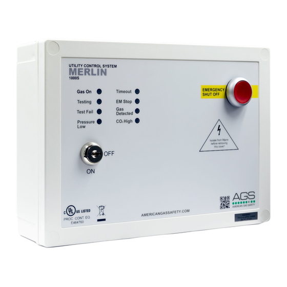
Merlin 1000S
Gas Utility Controller
3.2
LED STATUS
POWER
When the system is connected to mains supply, the Red LED of the AGS Logo located in the
bottom right corner of the panel will illuminate.
When no power is present, this LED will not light up.
RED = OK
OFF = No power to 1000S, a loose wire/ribbon connection or the fuse may not be intact.
GAS ON
When the key switch is turned on, the Merlin 1000S will check the installation for gas leaks.
If gas proving is successful, the gas valve will open and the GAS ON LED will illuminate.
GREEN = Gas On
OFF = Gas Off
TESTING
This LED will illuminate GREEN for approximately 30 seconds when the panel is checking the
integrity of the gas installation upon start up.
GREEN = proving the gas line, do NOT operate any appliances.
TEST FAIL
Under normal working conditions this LED is off.
When the panel detects a gas leak on start-up, the LED will illuminate and the gas valve will
remain closed.
OFF = OK
AMBER = Gas proving failed
PRESSURE LOW
Under normal working conditions the LED is off.
The LED will illuminate when the pressure of gas supply drops below 0.17psi for 10 seconds and
the gas valve will close.
OFF = OK
AMBER = Gas supply pressure low.
TIMEOUT
Under normal working conditions this LED is off. This LED will illuminate upon auto-shut down
OFF = OK
AMBER = auto-shut down
EM STOP
If an emergency shut off button (either remote or on the panel) is pressed, the LED will
illuminate and the gas will be shut off. The EM Stop button must be re-set before restarting the
system.
OFF = OK
AMBER = EM Stop button pressed
Rev: 05 Date: 29-10-18
User & Installation Manual
6
