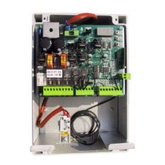
Dea 124RR Instruções e avisos - Página 4
Procurar online ou descarregar pdf Instruções e avisos para Painel de controlo Dea 124RR. Dea 124RR 11 páginas. Control board 24v for gate automation operating

1-2
24 V a.c. transformer power supply input
24 V a.c.
3-4
24 V d.c. battery power supply input (Follow carefully polarity indications)
24 V Batt
5-6
Free contact max. capacity 5 A : this contact can be used to control an open gate
warning light (P27=0) or a courtesy lamp (P27≠0)
LC/SCA
Flashing light output 24 V d.c. max 15W art. Lumy 24S The intermittent output does not
7-8
demand the use of a flashing light card.
LAMP
9
Common safety devices
COM
9-10
+24 V d.c. power supply output for controlled safety devices. To be used as power
supply of photocell transmitters (in all cases) and of safety devices when testing these
+24VAUX
latter before each operation
9-11
+24 V d.c. power supply output for auxiliary circuits and uncontrolled safety devices To
be used as power supply of any auxiliary devices, photocell receivers (in all cases), and
+24VSIC
of safety devices when testing these latter before each operation
Motor output 24 V d.c. max 70W
M
12-13
14
N.C. input limit switch while opening. If unused, short circuit to terminal n° 21
FCA
15
N.C. input limit switch while closing. If unused, short circuit to terminal n° 21
FCC
16
N.O. open input. If activated, it opens or closes both motors. It can work in "reversal"
START
mode (P25=0) or "step-by-step" mode (P25=1)
17
N.O. pedestrian opening input. If activated, it opens the motor
PEDON
18
N.C. stop input. If activated, it stops the movement of both motors during any opera-
STOP
tion. If unused, short circuit to terminal n° 21
19
N.C. Photocell input. In case of activation it reverses the movement only while closing
(P26=0) or it reverses the movement while closing and stops while opening (P26=1).
FOTOC
If unused, short circuit to the terminal n°21
20
N.C. leaf safety device input. In case of activation it reverses the movement (P18=0) or
it stops it (P18=1). If unused, short circuit to the terminal n°21
SIC
21
Common inputs
COM
22
Aerial ground input
Aerial signal input
23
8 USE INSTRUCTIONS
Press on the "OK" key to check if all inputs have been properly connected.
After making all connections to the terminal board, remember to short-circuit, whenever needed, any
unused input (see "connection to the control board") and power the card: on the display you will read for
a few seconds "rES-" followed by the symbol "----" which stands for gate closed.
8.1 Visualisation of inputs status
Operating instructions and warnings
Table 1 Terminal board connection
15
1 2 4 R R
R
