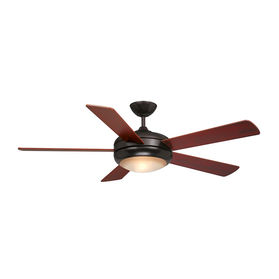
aireRyder FN52243 Manual - Página 7
Procurar online ou descarregar pdf Manual para Ventilador aireRyder FN52243. aireRyder FN52243 8 páginas.

3.
Fig.16
6.
Antenna:
DO NOT CUT
OR SPLICE
Safety Cable Hook
Safety
Cable
Fig.18.
Tuck the Antenna into the Canopy.
Push the Canopy upwards, lining up
the keyholes on the bottom with the
screws on the Hanger Bracket.
Twist the Canopy to lock it in place,
then tighten the screws to secure it.
Light Switch Control Function
This remote control option will allow
the use of a standard wall switch
(connected to the fan power) to
control the ceiling fan and light kit.
OFF
HI
MED
ON/OFF
O F F
H I
O N / O F F
M E D
LOW
DIMMER
D I M M E R
L O W
Fig.21
2.
4.
1.
Receiver
Hanger
Bracket
Hanger
Ball
Fig.17.
Fig.19
Install the bulb. Push the Glass upwards
and turn to install.
Use the reverse switch to have the Fan
turn in the opposite direction.
Light Control:
Flip the wall switch from ON to OFF
and then back to ON quickly (Less than
0.5 seconds) to change the light
setting. The receiver will emit a short
"beep" when the light setting has been
successfully changed. The lights will
cycle from current setting downward,
and then to high setting.
Install the battery to the transmitter (9V, not included).
* Press "HI" to turn on the fan at high speed.
* Press "MED" button to turn the fan in medium speed.
* Press "LOW" button to turn the fan in low speed.
* Press "OFF" button to turn off the fan.
* Press and release the "ON/OFF" button quickly to turn
on or off the light.
* Press and release the "DIMMER" button to adjust the
illumination of light.
Make wire connections:
5.
1) The Motor white wire to the white "To Motor N" wire from
Receiver with a wire nut.
2) The Motor black wire to the black "To Motor L" wire from
Receiver with a wire nut.
3) The Motor blue wire to the blue "For Light" wire from
Receiver with a wire nut.
4) The white wire from Outlet Box to the white "AC in N" wire
from Receiver with a wire nut.
5) The red wire from Outlet Box to the black "AC in L" wire from
Receiver with a wire nut.
6) The ground wire from Outlet Box to the green ground wire
from the Hanger Ball and the green ground wire from the
Hanger Bracket with a wire nut.
Make sure all of wire nuts are connected firmly.
*** Tuck all wire nuts and wires carefully up into the Outlet Box,
EXCEPT antenna, which should remain outside Outlet Box.
Hang the safety cable into the safety cable hook.( See Fig.17)
Reverse Switch
PAGE: 3 / 4
Fig.20
Turn ON the electric power at the
main fuse or circuit breaker box.
Fan Control:
Flip the wall switch from ON to
OFF and then back to ON Slower
(More than 0.5 seconds) to
change the fan speed. The speeds
will cycle from current setting
downward, and then to the high
setting. The receiver will emit a
series of "beeps" when the fan
speed has been successfully
changed to:
High - 4 long "beeps"
Medium - 3 long "beeps"
Low - 2 long "beeps"
Slow Low - 1 long "beep"
Stop - 4 short "beeps"
071009
