Major tech MT700 Manual de instruções - Página 12
Procurar online ou descarregar pdf Manual de instruções para Equipamento de teste Major tech MT700. Major tech MT700 16 páginas. Voltage & current tester

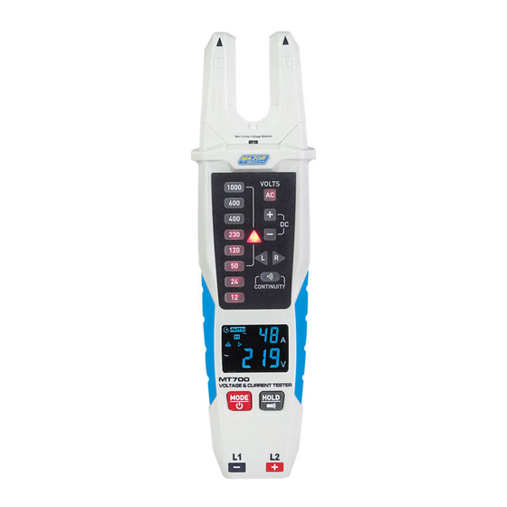
4.6. Rotary Field Indication
• The voltage testers are equipped with a double-pole rotary field
indicator.
• The rotary phase indication is always active. the symbols "R" or
"L" are always displayed, however the rotary direction can only
be determined within a thee-phase system, here the instrument
indicates the voltage between two external conductors.
• Connect the instrument Red Test Lead (L2+) with the supposed
phase L2 and the Black test lead (L1-) with the supposed phase
L1, the voltage and the rotary field direction are displayed.
• "R"signifies that the supposed phase L1 is the actual phase L1
and the supposed phase L2 is the actual phase L2, "L" signifies
that the supposed phase L1 is the actual phase L2 and the
supposed phase L2 is the actual phase L1.
• The test result table is as follows:
Black Test Red Test
Pen (L1-)
L1
L2
L3
L1
L2
L3
L1/L2/L3
N/PE
• Effective for voltages greater
than 80Vrms.
4.7. Resistance Test
• The Tester measures low ohm resistances between 1 and 1999
at a resolution of 1 . Ω
• When you do a Resistance test make sure the UUT (Unit under
test) is not live.
4.8. Continuity Test
• When you do a continuity test make sure the UUT (Unit under
test) is not live.
• The continuity test is only possible when batteries are installed
and in good condition, a signal sound is audible for continuity and
the LED for continuity LED is illuminated.
12
Test Results
Pen (L2+)
L2
R
L3
R
L1
R
L3
L
L1
L
L2
L
N/PE
No Result
L1/L2/L3
No Result
Ω
Ω
