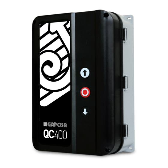
GAPOSA QC400 Manual - Página 7
Procurar online ou descarregar pdf Manual para Motor GAPOSA QC400. GAPOSA QC400 16 páginas. Automatic control unit for three/single-phase motors with digital or mechanical limits

3 DIPSWITCH FUNCTIONS
NOTE OPERATING LOGIC
A
Dead-man OPEN/CLOSE
B
Impulse OPEN/CLOSE
C
Impulse OPEN / Deadman CLOSE
OPTIONS
D
Auto close (after delay time)
E
Electronic after run / edge monitoring
Force control (Multiturn)
F
(NOT AVAILABLE AT THE MOMENT)
Force control fine sense
(NOT AVAILABLE AT THE MOMENT)
Go Function Standard
G
Go Function Special (Start/Stop, radio)
Edge super fast reverse 0.05 sec
(NOT AVAILABLE AT THE MOMENT)
Edge reverse time – Normal
(NOT AVAILABLE AT THE MOMENT)
LIMIT SWITCH TYPE SELECTION
Mechanical limit switch
Electronic encoded limit switch
NOTE
SAFETY LOGIC
A
When an obstacle is detected during the DOWN operation the movement is stopped with a brief upward movement; It has no effect on the way UP.
When an obstacle is detected during the UP operation It has no effect. During the DOWN operation the movement is reversed until the opening
B
limit switch.
When an obstacle is detected during the UP operation It has no effect. During the DOWN operation the movement is reversed until the opening
C
limit switch
This function can only be selected when DIP2 is in ON position and safeties are connected. The auto closing time is preset to 15 Sec. To reset
a new time setting, run the door to open position and push both open and close buttons for minimum 5 Sec. When the red LED START flashing,
D
release the buttons. After that wait until the new desired auto closing time and then push the close button. Max auto closing time is about 4 min.
If max setting time is exceeded, the red LED STOP flashing and the auto close time is adjusted back to 15 Sec. Auto closing time is remembered
after power OFF. Auto closing can also be disabled with a switch connected to X16 connector.
When DIP4 is in ON position, the edge monitoring is selected. When adjusting the limits, DIP4 is set to OFF. Close limit switch shall be adjusted
E
such as the door is stopped 5 cm before the floor. After this change DIP4 to ON. (PNE edge only). Clearing fail is done by closing the door in dead-
man mode (hold to run mode), keeping the close push-button ON until the door is stopped by signal from safety device.
Force control setting: Change DIP5 to ON position. (Fail LED and LED on membrane keypad showing long flash). The door shall be mounted and
limits adjusted before activating the force control. With DIP5=ON the force control is automatic learned by the first 2 fully open cycles without
F
stop, starting in closed position. The controller will work as a dead-man controller until all force values are learned. If the control only run by
small step when closing – Tacho pulses is missing.
G
Special technical information - see par. 10
ADDITIONAL FEATURES
Photo
Photo circuit is tested before every close operation. Photo circuit must be connected during the setting process.
Service showing for every 1000 openings (see separate LED guidance). Reset of service is done by activating the electronic counter and keeping
Service
this active for minimum 4 minutes. The controller will then automatic switch to normal operation with service LED out. The service function is
only activating the service LED. (NOT AVAILABLE AT THE MOMENT)
The door cannot close when there is an error in the photo or safety edge. By a special code the door can close one time in hold to run mode.
Safety
Press and hold STOP when pressing 222111 (2 = DOWN push button and 1 = OP push button). Code must be pressed within 6 sec
1
2
3
4
OFF
OFF
-
-
ON
ON
-
-
ON
OFF
-
-
ON
ON
ON
-
-
-
-
ON
-
-
-
-
-
-
-
-
-
ON
-
-
-
ON
-
-
-
-
-
-
-
-
-
-
-
-
-
-
-
-
-
-
DIP
ON
OFF
1 2 3 4 5 6 7 8 9 10
DIP
5
6
7
8
-
-
-
-
-
-
-
-
-
-
-
-
-
-
-
-
-
-
-
-
ON
-
-
-
-
ON
-
-
-
-
OFF
-
-
-
ON
-
-
-
-
ON
-
-
-
OFF
-
-
-
-
-
-
-
-
S3
9
10
-
-
-
-
-
-
-
-
-
-
-
-
-
-
-
-
-
-
-
-
ON
-
-
OFF
-
ON
7
