Cosel ADA750F Manual de instruções - Página 6
Procurar online ou descarregar pdf Manual de instruções para Fonte de alimentação Cosel ADA750F. Cosel ADA750F 11 páginas.
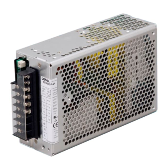
ADA
2.4 Expectancy life and warranty
¡Expectancy life
The expectancy life is as follows. The mean of load factor 100%
depends on installation condition, refer to SPECIFICATION.
Average ambient
Installation
temperature
condition
(year)
Ta = 30C
*
Convection
Ta = 40C
(Installation A)
Ta = 50C
Ta = 30C
Forced air
*
Ta = 40C
Ta = 50C
*Refer to 2.3 Derating
¡Warranty
The warranty is 5 years when average ambient temperature of
year is Ta = 40C or less and load factor is average 50% or less.
However, the warranty is 3 years when average ambient temper-
ature of year is Ta = 50C or less and load factor is series 100%.
2.5 Current monitor
¡It is possible to monitor load current by measuring CB voltage that
is between CB terminal and -V terminal. The relation between CB
voltage and load current is shown in Figs.2.4 to 2.6.
Note : Figs.2.4 to 2.6 are references, and are not meant to be
taken as guaranteed values.
¡Ensure that voltage measurement between CB and -V terminals
is carried out with equipment that has suffi cient input impedance
(testers, etc.). If this equipment has low input impedance, then the
relationship between CB voltage and output current will change.
Additionally, please be aware that a short between terminals may
result in damage to internal components.
¡Please use twist pair cable or shield cable between CB terminal
and -V terminal, or the operation may be mulfunction.
¡Please use an oscilloscope for pulse loads.
12
10
8
6
4
2
0
10
Load current (A)
Fig.2.4 Load current conversion graph (ADA600F-24)
ADA-12
Artisan Technology Group - Quality Instrumentation ... Guaranteed | (888) 88-SOURCE | www.artisantg.com
AC-DC Power Supplies Enclosed Type
Load factor
50%
100%
More than 10 years
More than 10 years
More than 10 years
6 years
5 years
3 years
More than 10 years
More than 10 years
More than 10 years
6 years
5 years
3 years
20
30
40
Instruction Manual
16
14
12
10
8
6
4
2
0
20
Load current (A)
Fig.2.5 Load current conversion graph (ADA750F-24)
16
14
12
10
8
6
4
2
0
20
40
Load current (A)
Fig.2.6 Load current conversion graph (ADA1000F-24)
3 Series Operation and
Parallel Operation
3.1 Series operation
¡Series operation is available by connecting the outputs of two or
more power supplies with the same output voltage, as shown be-
low. Output current in series connection should be lower than the
lowest rated current in each unit.
¡Parallel operation is show in Fig.3.1.
+
Power
Supply
Load
+
Power
Supply
Fig.3.1 Examples of series operation
3.2 Parallel operation/master-slave operation
¡Parallel operation is available by connecting below.
¡As variance of output current drew from each power supply is
maximum 10%, the total output current must not exceed the value
determined by the following equation.
The rated
Output current in
=
parallel operation
current per unit
When the number of units in parallel operation increases, input
current increases at the same time. Adequate wiring design for
input circuitry is required, such as circuit pattern, wiring and cur-
rent capacity for equipment.
In parallel operation, the maximum operative number of units is 5.
40
60
80
60
80
100
+
Power
Supply
Load
+
Load
Power
Supply
X (Number of unit) X0.9